
Data Sheet

Page 66
RFM69HCW
Tel: + 86-755-82973805 Fax: +86- 755-82973550 E-mail: sales@hoperf.com http:/ / www.hoperf.com
ADVANCED COMMUNICATIONS & SENSING DATASHEET
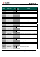
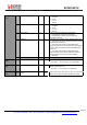
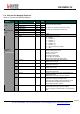
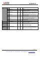
6.3. Transmitter Registers
Table 25 Transmitter Registers
Name
(Address)
Bits Variable Name Mode
Default
Value
Description
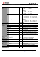
7 Pa0On * rw 1 Enables PA0, connected to RFIO and LNA
6 Pa1On * rw 0 Enables PA1, on PA_BOOST pin
5 Pa2On * rw 0 Enables PA2, on PA_BOOST pin
RegPaLevel
(0x11)
4-0 OutputPower rw 11111 Output power setting, with 1 dB steps
Pout = -18 + OutputPower [dBm] , with PA0
Pout = -18 + OutputPower [dBm] , with PA1**
Pout = -14+ OutputPower [dBm] , with PA1 and PA2**
Pout = -11 + OutputPower [dBm] , with PA1 and PA2, and
high Power PA settings (refer to section 3.3.7)**
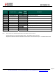
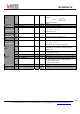
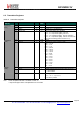
7-4 - r 0000 unused
RegPaRamp
(0x12)
3-0 PaRamp rw 1001 Rise/Fall time of ramp up/down in FSK
0000 → 3.4 ms
0001 → 2 ms
0010 → 1 ms
0011 → 500 us
0100 → 250 us
0101 → 125 us
0110 → 100 us
0111 → 62 us
1000 → 50 us
1001 → 40 us
1010 → 31 us
1011 → 25 us
1100 → 20 us
1101 → 15 us
1110 → 12 us
1111 → 10 us
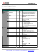
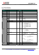
7-5 - r 000 unused
4 OcpOn rw 1 Enables overload current protection (OCP) for the PA:
0 → OCP disabled
1 → OCP enabled
RegOcp
(0x13)
3-0 OcpTrim rw 1010 Trimming of OCP current:
Imax = 45 + 5
⋅
OcpTrim mA
95 mA OCP by default
Note *Power Amplifier truth table is available in Table 10
** Only the16 upper values of OutputPower are accessible