
Data Sheet

Page 63
RFM69HCW
Tel: + 86-755-82973805 Fax: +86- 755-82973550 E-mail: sales@hoperf.com http:/ / www.hoperf.com
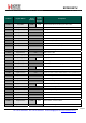
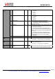
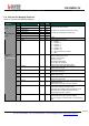
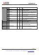
6.2. Common Configuration Registers
Table 24 Common Configuration Registers
Name
(Address)
Bits Variable Name Mode
Default
Value
Description
RegFifo
(0x00)
7-0 Fifo rw 0x00 FIFO data input/output
7 SequencerOff rw 0 Controls the automatic Sequencer (see section 4.2 ):
0 → Operating mode as selected with Mode bits in
RegOpMode is automatically reached with the Sequence
r
1 → Mode is forced by the user
6 ListenOn rw 0 Enables Listen mode, should be enabled whilst in
Standby mode:
0 → Off (see section 4.3)
1 → On
5 ListenAbort w 0 Aborts Listen mode when set together with ListenOn=0
See section 4.3.4 for details
Always reads 0.
4-2 Mode rw 001 Transceiver’s operating modes:
000 → Sleep mode (SLEEP)
001 → Standby mode (STDBY)
010 → Frequency Synthesizer mode (FS)
011 → Transmitter mode (TX)
100 → Receiver mode (RX)
others → reserved
; Reads the value corresponding to
the current module mode
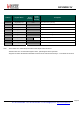
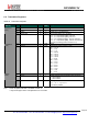
RegOpMode
(0x01)
1-0 - r 00 unused
7 - r 0 unused
6-5 DataMode rw 00 Data processing mode:
00 → Packet mode
01 → reserved
10 → Continuous mode with bit synchronizer
11 → Continuous mode without bit synchronizer
4-3 ModulationType rw 00 Modulation scheme:
00 → FSK
01 → OOK
10 - 11 → reserved
2 - r 0 unused
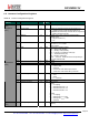
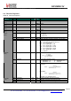
RegDataModul
(0x02)
1-0 ModulationShaping rw 00 Data shaping:
in FSK:
00 → no shaping
01 → Gaussian filter, BT = 1.0
10 → Gaussian filter, BT = 0.5
11 → Gaussian filter, BT = 0.3
in OOK:
00 → no shaping
01 → filtering with f
cutoff
= BR
10 → filtering with f
cutoff
= 2*BR
11 → reserved
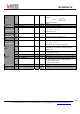
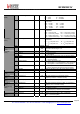
RegBitrateMsb
(0x03)
7-0 BitRate(15:8) rw 0x1a MSB of Bit Rate (Chip Rate when Manchester encoding is
enabled)