
Data Sheet

Page 39
RFM69HCW
Tel: + 86-755-82973805 Fax: +86- 755-82973550 E-mail: sales@hoperf.com http:// www.hoperf.com
4.3. Listen Mode
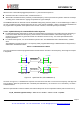
The circuit can be set to Listen mode, by setting ListenOn in RegOpMode to 1 while in Standby mode. In this mode,
RFM69HCW spends most of the time in Idle mode, during which only the RC oscillator runs. Periodically the receiver is
woken up and listens for an RF signal. If a wanted signal is detected, the receiver is kept on and the data is demodulated.
Otherwise, if a wanted signal hasn't been detected after a pre-defined period of time, the receiver is disabled until the next
time period.
This periodical Rx wake-up requirement is very common in low power applications. On RFM69HCW it is handled locally by
the
Listen mode block without using uC resources or energy.
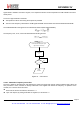
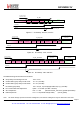
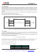
The simplified timing diagram of this procedure is illustrated in Figure 21.
t
ListenIdle
Rx
Idle
Rx
time
t
ListenRx
t
ListenRx
Figure 20. Listen Mode Sequence (no wanted signal is received)
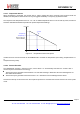
4.3.1. Timings
The duration of the Idle phase is given by t
ListenIdle
. The time during which the receiver is on and waits for a signal is given
by t
ListenRx
. t
ListenRx
includes the wake-up time of the receiver, described in section 4.2.3. This duration can be
programmed in the configuration registers via the serial interface.
Both time periods t
ListenRx
and t
ListenIdle
(denoted t
ListenX
in the following text) are fixed by two parameters from the
configuration register and are calculated as follows:
t
ListenX
= ListenCoefX ∗
Listen
Re
solX
where ListenResolX is the Rx or Idle resolution and is independently programmable on three values (64us, 4.1ms or
262ms), whereas ListenCoefX is an integer between 1 and 255. All parameters are located in RegListen registers.
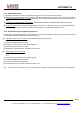
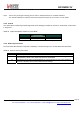
The timing ranges are tabulated in Table 17 below.
Table 17 Range of Durations in Listen Mode
ListenResolX Min duration
( ListenCoef = 1 )
Max duration
( ListenCoef = 255 )
01
64
us
16
ms
10
4.1
ms
1.04
s
11
0.26
s
67
s