
Data Sheet

Page 23
RFM69HCW
Tel: + 86-755-82973805 Fax: +86- 755-82973550 E-mail: sales@hoperf.com http:// www.hoperf.com
Dec
imator
Processing
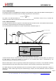
3.4. Receiver Description
The RFM69HCW features a digital receiver with the analog to digital conversion process being performed directly
following the LNA-Mixers block. The zero-IF receiver is able to handle (G)FSK and (G)MSK modulation. ASK and OOK
modulation is, however, demodulated by a low-IF architecture. All the filtering, demodulation, gain control, synchronization
and packet handling is performed digitally, which allows a very wide range of bit rates and frequency deviations to be
selected. The receiver is also capable of automatic gain calibration in order to improve precision on RSSI measurements.
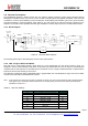
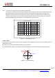
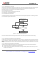
3.4.1. Block Diagram
Rx
Cal
ibration
Reference
RFIO
From
PA1
LNA
Single
to
Differential
Mi
x
ers
©/
⊗
Modulators
Channel
Fil
ter
DC
Cancel
lation
Compl ex
Fi
lter
CORDIC
Phase
Out put
Module
Output
RSSI
FSK
Demodulator
OOK
Demodul
ator
Local
Os
c
illator
AFC
By
pass
ed
in
FSK
AGC
Figure 6. Receiver Block
Diagram
The following sections give a brief description of each of the receiver blocks.
3.4.2. LNA - Single to Differential Buffer
The LNA uses a common-gate topology, which allows for a flat characteristic over the whole frequency range. It is
designed to have an input impedance of 50 Ohms or 200 Ohms (as selected with bit LnaZin in RegLna), and the parasitic
capacitance at the LNA input port is cancelled with the external RF choke. A single to differential buffer is implemented to
improve the second order linearity of the receiver.
The LNA gain, including the single-to-differential buffer, is programmable over a 48 dB dynamic range, and control is either
manual or automatic with the embedded AGC function.
Note In the specific case where the LNA gain is manually set by the user, the receiver will not be able to properly handle
FSK signals with a modulation index smaller than 2 at an input power greater than the 1dB compression point,
tabulated in section 3.4.3.
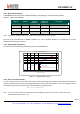
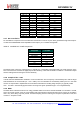
Table 12 LNA Gain Settings
LnaGainSelect LNA Gain Gain Setting
000 Any of the below, set by the AGC loop -
001 Max gain G1
010 Max gain - 6 dB G2
011 Max gain - 12 dB G3
100 Max gain - 24 dB G4
101 Max gain - 36 dB G5
110 Max gain - 48 dB G6
111 Reserved -