
Data Sheet

Page 22
RFM69HCW
Tel: + 86-755-82973805 Fax: +86- 755-82973550 E-mail: sales@hoperf.com http:// www.hoperf.com
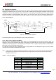
Pout on PA0 [dB
m
]
Pout on PA1 [dB
m
]
Pout
on
PA1+PA2
[dBm]
P
out on
P
A
1+
P
A
2 wi th 20dB m
s
ettings [dB
m
]
Pout
[dBm]
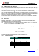
3.3.7. High Power Settings
The RFM69HCW has a high power +20 dBm capability on PA_BOOST pin, with the following settings:
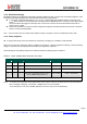
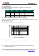
Table 11 High Power Settings
Register
Address
Value for
High Power
Value for Rx
or PA0 use
Description
RegOcp
0x13
0x0F
0x1x
OCP control
RegTestPa1
0x5A
0x5D
0x55
High power PA control
RegTestPa2
0x5C
0x7C
0x70
High power PA control
Note High Power settings MUST be turned off when using PA0, and in Receive mode
The Duty Cycle of transmission at +20dBm is limited to 1%, with a maximum VSWR of 3:1 at antenna port, over the
standard operating range [-40;+85°C].
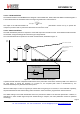
3.3.8. Output Power Summary
The curves below summarize the possible PA options on the RFM69HCW:
P
o
ut vs.
P
r
o
g
ram m ed
P
o
w
er
22
18
14
10
6
2
-2
-6
-10
-14
-18
-22
-18 -1 4 -10 - 6 -2 2 6 10 14
18
Pr
o
g
r
am m
e
d
Po
w
e
r
[d
Bm
]
Figure 5. Output Power
Curves
3.3.9. Over Current Protection
An over current protection block is built-in the module. It helps preventing surge currents required when the transmitter is
used at its highest power levels, thus protecting the battery that may power the application. The current clamping value is
controlled by OcpTrim bits in RegOcp, and is calculated with the following formula:
Imax = 45 + 5
⋅
OcpTrim mA
Note Imax sets a limit on the current drain of the Power Amplifier only, hence the maximum current drain of the
RFM69HCW is equal to Imax + I
FS