
Data Sheet


Page 16
RFM69HCW
Tel: + 86-755-82973805 Fax: +86- 755-82973550 E-mail: sales@hoperf.com http:/ / www.hoperf.com
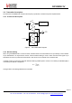
3. Module Description
This section describes in depth the architecture of the RFM69HCW low-power, highly integrated
transceiver.
3.1. Power Supply Strategy
The RFM69HCW employs an advanced power supply scheme, which provides stable operating characteristics over the
full temperature and voltage range of operation. This includes the full output power of +20dBm maintained from 2.4 to 3.6V.
The RFM69HCW can be powered from any low-noise voltage source via pins VBAT1 and VBAT2. Decoupling capacitors
should be connected, as suggested in the reference design, on VR_PA, VR_DIG and VR_ANA pins to ensure a correct
operation of the built-in voltage regulators.
3.2. Frequency Synthesis
The LO generation on the RFM69HCW is based on a state-of-the-art fractional-N PLL. The PLL is fully integrated with
automatic calibration.
3.2.1. Reference Oscillator
The crystal oscillator is the main timing reference of the RFM69HCW. It is used as a reference for the frequency
synthesizer and as a clock for the digital processing.
The XO startup time, TS_OSC, depends on the actual XTAL being connected on pins XTA and XTB. When using the built-
in sequencer, the RFM69HCW optimizes the startup time and automatically triggers the PLL when the XO signal is stable.
To manually control the startup time, the user should either wait for TS_OSC max, or monitor the signal CLKOUT which
will only be made available on the output buffer when a stable XO oscillation is achieved.