
Data Sheet


Page 12
RFM69HCW
Tel: + 86-755-82973805 Fax: +86- 755-82973550 E-mail: sales@hoperf.com http:/ / www.hoperf.com
2.3 Module Specification
The tables below give the electrical specifications of the transceiver under the following conditions: Supply voltage VBAT1=
VBAT2=VDD=3.3 V, temperature = 25 °C, F
RF
= 915 MHz, Pout = +20dBm, 2-level FSK modulation without pre-filtering,
FDA = 5 kHz, Bit Rate = 4.8 kb/s and terminated in a matched 50 Ohm impedance, unless otherwise specified.
Note Unless otherwise specified, the performances in the other frequency bands are similar or better.
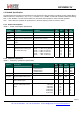
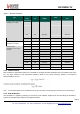
2.3.1. Power Consumption
Table 4 Power Consumption Specification
Symbol Description Conditions Min Typ Max Unit
IDDSL
Supply current in Sleep mode
- 0.1 1 uA
IDDIDLE Supply current in Idle mode RC oscillator enabled - 1.2 - uA
IDDST Supply current in Standby mode Crystal oscillator enabled - 1.25 1.5 mA
IDDFS Supply current in Synthesizer
mode
- 9 - mA
IDDR Supply current in Receive mode
- 16 - mA
IDDT Supply current in Transmit mode
with appropriate matching, sta-
ble across VDD range
RFOP = +20 dBm, on PA_BOOST
RFOP = +17 dBm, on PA_BOOST
RFOP = +13 dBm, on RFIO pin
RFOP = +10 dBm, on RFIO pin
RFOP = 0 dBm, on RFIO pin
RFOP = -1 dBm, on RFIO pin
-
-
-
-
-
-
130
95
45
33
20
16
-
-
-
-
-
-
mA
mA
mA
mA
mA
mA
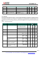
2.3.2. Frequency Synthesis
Table 5 Frequency Synthesizer Specification
Symbol
Description
Conditions
Min
Typ
Max
Unit
FR
Synthesizer Frequency Range
315MHz Module
433MHz Module
868MHz Module
915MHz Module
290
424
862
890
340
510
890
1020
MHz
MHz
MHz
MHz
FXOSC Crystal oscillator frequency For All Module - 32 - MHz
TS_OSC Crystal oscillator wake-up time
- 250 500 us
TS_FS Frequency synthesizer wake-up
time to PllLock signal
From Standby mode - 80 150 us
TS_HOP Frequency synthesizer hop time
at most 10 kHz away from the
target
200 kHz step
1 MHz step
5 MHz step
7 MHz step
12 MHz step
20 MHz step
25 MHz step
-
-
-
-
-
-
-
20
20
50
50
80
80
80
-
-
-
-
-
-
-
us
us
us
us
us
us
us