
Data Sheet


Absolute maximum ratings and operating conditions TSH80, TSH81, TSH82, TSH84
6/30 DocID009413 Rev 9
2 Absolute maximum ratings and operating conditions
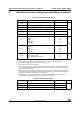
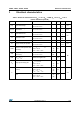
Table 1. Absolute maximum ratings
Symbol Parameter Value Unit
V
CC
Supply voltage
(1)
1. All voltage values, except differential voltage are with respect to the network ground terminal.
14
VV
id
Differential input voltage
(2)
2. The differential voltage is the non inverting input terminal with respect to the inverting terminal.
±2
V
i
Input voltage
(3)
3. The magnitude of input and output must never exceed V
CC
+0.3 V.
±6
T
oper
Operating free air temperature range -40 to +85
°CT
stg
Storage temperature -65 to +150
T
j
Maximum junction temperature 150
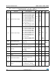
R
thjc
Thermal resistance junction-to-case
(4)
SOT23-5
SO8
TSSOP8
TSSOP14
4. Short-circuits can cause excessive heating.
80
28
37
32
°C/W
R
thja
Thermal resistance junction-to-ambient area
SOT23-5
SO8
TSSOP8
TSSOP14
250
157
130
110
ESD
HBM: human body model
(5)
MM: machine model
(6)
CDM: charged device model
(7)
5. Human body model: a 100 pF capacitor is charged to the specified voltage, then discharged through
a 1.5 kΩ resistor between two pins of the device. This is done for all couples of connected pin combinations
while the other pins are floating.
6. Machine model: a 200 pF capacitor is charged to the specified voltage, then discharged directly between
two pins of the device with no external series resistor (internal resistor < 5 Ω). This is done for all couples of
connected pin combinations while the other pins are floating.
7. Charged device model: all pins and package are charged together to the specified voltage and then
discharged directly to ground through only one pin. This is done for all pins.
2
0.2
1.5
kV
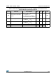
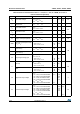
Table 2. Operating conditions
Symbol Parameter Value Unit
V
CC
Supply voltage 4.5 to 12
VV
IC
Common mode input voltage range V
CC
-
to (V
CC
+
-1.1)
Standby (pin 8) Threshold on pin 8 for TSH81 (V
CC
-
) to (V
CC
+
)