
Data Sheet


© 2009 Microchip Technology Inc. DS22039D-page 15
MCP4725
4.0 TERMINOLOGY
4.1 Resolution
The resolution is the number of DAC output states that
divide the full scale range. For the 12-bit DAC, the
resolution is 2
12
or the DAC code ranges from 0 to
4095.
4.2 LSB
The least significant bit or the ideal voltage difference
between two successive codes.
EQUATION 4-1:
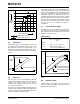
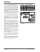
4.3 Integral Nonlinearity (INL) or
Relative Accuracy
INL error is the maximum deviation between an actual
code transition point and its corresponding ideal
transition point (straight line). Figure 2-5 shows the INL
curve of the MCP4725. The end-point method is used
for the calculation. The INL error at a given input DAC
code is calculated as:
EQUATION 4-2:
FIGURE 4-1: INL Accuracy.
4.4 Differential Nonlinearity (DNL)
Differential nonlinearity error (Figure 4-2) is the
measure of step size between codes in actual transfer
function. The ideal step size between codes is 1 LSB.
A DNL error of zero would imply that every code is
exactly 1 LSB wide. If the DNL error is less than 1 LSB,
the DAC guarantees monotonic output and no missing
codes. The DNL error between any two adjacent codes
is calculated as follows:
EQUATION 4-3:
LSB
Ideal
V
REF
2
n
-------------
V
Full Scale
V
Zero Scale
–()
2
n
1–
------------------------------------------------------------------==
Where:
V
REF
= The reference voltage = V
DD
in the
MCP4725. This V
REF
is the ideal
full scale voltage range
n = The number of digital input bits.
(n = 12 for MCP4725)
INL
V
OUT
V
Ideal
–()
LSB
---------------------------------------=
Where:
V
Ideal
= Code*LSB
V
OUT
= The output voltage measured at
the given input code
010001000
Analog
Output
(LSB)
DAC Input Code
011 111100 101
1
2
3
4
5
6
0
7
110
Ideal Transfer Function
Actual Transfer Function
INL = < -1 LSB
INL = 0.5 LSB
INL = - 1 LSB
DNL
Δ
V
OUT
LSB–
LSB
----------------------------------=
Where:
ΔV
OUT
= The measured DAC output
voltage difference between two
adjacent input codes.