
Data Sheet


Si4702/03-C19
6 Rev. 1.1
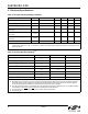
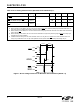
Figure 1. Reset Timing Parameters for Busmode Select Method 1 (GPIO3 = 0)
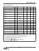
Table 4. Reset Timing Characteristics (Busmode Select Method 1)
1,2,3
Parameter Symbol Test Condition Min Typ Max Unit
RST
pulse width and GPIO3 Setup
to RST
t
GSRST1
4
GPIO3 = 0 100 — — µs
SEN
and SDIO Setup to RST t
SRST1
30 — — ns
SEN
, SDIO, and GPIO3 Hold from
R
ST
t
HRST1
30 — — ns
Notes:
1. When selecting 2-wire Mode, the user must ensure that a 2-wire start condition (falling edge of SDIO while SCLK is
high) does not occur within 300 ns before the rising edge of RST
.
2. When selecting 3-wire Mode, the user must ensure that a rising edge of SCLK does not occur within 300 ns before the
rising edge of RST
.
3. When selecting 2-wire mode, the user must ensure that SCLK is high during the rising edge of RST
, and stays high
until after the 1st start condition.
4. If GPIO3 is driven low by the user, then minimum t
GSRST1
is only 30 ns. If GPIO3 is hi-Z, then minimum t
GSRST1
is
100 µs, to provide time for an on-chip 1 M pulldown device (active while RST is low) to discharge the pin.
70%
30%
SEN,
SDIO
70%
30%
GPIO3
70%
30%
t
GSRST1
RST
t
HRST1
t
SRST1