
Data Sheet

www.ti.com
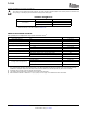
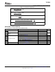
RECOMMENDED OPERATING CONDITIONS
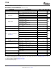
DISSIPATION RATINGS
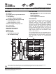
TLC5940
SLVS515C – DECEMBER 2004 – REVISED OCTOBER 2007
MIN NOM MAX UNIT
DC CHARACTERISTICS
V
CC
Supply Voltage 3 5.5 V
V
O
Voltage applied to output (OUT0 – OUT15) 17 V
V
IH
High-level input voltage 0.8 V
CC
V
CC
V
V
IL
Low-level input voltage GND 0.2 V
CC
V
I
OH
High-level output current V
CC
= 5V at SOUT – 1 mA
I
OL
Low-level output current V
CC
= 5V at SOUT, XERR 1 mA
OUT0 to OUT15, V
CC
< 3.6V 60 mA
I
OLC
Constant output current
OUT0 to OUT15, V
CC
> 3.6V 120 mA
V
(VPRG)
EEPROM program voltage 20 22 23 V
T
A
Operating free-air temperature range -40 85 ° C
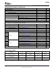
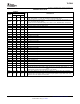
AC CHARACTERISTICS
V
CC
= 3 V to 5.5 V, T
A
= – 40 ° C to 85 ° C (unless otherwise noted)
f
(SCLK)
Data shift clock frequency SCLK 30 MHz
f
(GSCLK)
Grayscale clock frequency GSCLK 30 MHz
t
wh0
/t
wl0
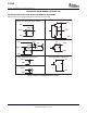
SCLK pulse duration SCLK = H/L (see Figure 11 ) 16 ns
t
wh1
/t
wl1
GSCLK pulse duration GSCLK = H/L (see Figure 11 ) 16 ns
t
wh2
XLAT pulse duration XLAT = H (see Figure 11 ) 20 ns
t
wh3
BLANK pulse duration BLANK = H (see Figure 11 ) 20 ns
t
su0
SIN to SCLK ↑
(1)
(see Figure 11 ) 5 ns
t
su1
SCLK ↓ to XLAT ↑ (see Figure 11 ) 10 ns
t
su2
VPRG ↑ ↓ to SCLK ↑ (see Figure 11 ) 10 ns
t
su3
Setup time VPRG ↑ ↓ XLAT ↑ (see Figure 11 ) 10 ns
t
su4
BLANK ↓ to GSCLK ↑ (see Figure 11 ) 10 ns
t
su5
XLAT ↑ to GSCLK ↑ (see Figure 11 ) 30 ns
t
su6
VPRG ↑ to DCPRG ↑ (see Figure 16 ) 1 ms
t
h0
SCLK ↑ to SIN (see Figure 11 ) 3 ns
t
h1
XLAT ↓ to SCLK ↑ (see Figure 11 ) 10 ns
t
h2
SCLK ↑ to VPRG ↑ ↓ (see Figure 11 ) 10 ns
Hold Time
t
h3
XLAT ↓ to VPRG ↑ ↓ (see Figure 11 ) 10 ns
t
h4
GSCLK ↑ to BLANK ↑ (see Figure 11 ) 10 ns
t
h5
DCPRG ↓ to VPRG ↓ (see Figure 11 ) 1 ms
t
prog
Programming time for EEPROM (see Figure 16 ) 20 ms
(1) ↑ and ↓ indicates a rising edge, and a falling edge respectively.
POWER RATING DERATING FACTOR POWER RATING POWER RATING
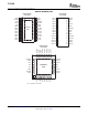
PACKAGE
T
A
< 25 ° C ABOVE T
A
= 25 ° C T
A
= 70 ° C T
A
= 85 ° C
28-pin HTSSOP with
3958mW 31.67mW/C 2533mW 2058mW
PowerPAD™
(1)
soldered
28-pin HTSSOP with PowerPAD™ 2026mW 16.21mW/ ° C 1296mW 1053mW
unsoldered
32-pin QFN
(1)
3482mW 27.86mW/ ° C 2228mW 1811mW
28-pin PDIP 2456mW 19.65mW/ ° C 1572mW 1277mW
(1) The PowerPAD is soldered to the PCB with a 2 oz. (56,7 grams) copper trace. See SLMA002 for further information.
Copyright © 2004 – 2007, Texas Instruments Incorporated Submit Documentation Feedback 3
Product Folder Link(s): TLC5940