
Data Sheet


www.ti.com
GSCLK
BLANK
GSPWM
Cyclen
1 2 3 1
GSPWM
Cyclen+1
OUT0
OUT1
OUT15
XERR
nxt
d
t
pd1
t
pd1
+t
d
t
pd1
+15xt
d
t
pd2
t
pd3
t
wh1
t
wl1
t
wl1
t
pd3
4096
t
h4
t
wh3
t
pd3
+nxt
d
t
su4
(Current)
(Current)
(Current)
SERIAL DATA TRANSFER RATE
f
(GSCLK)
+ 4096 f
(update)
f
(SCLK)
+ 193 f
(update)
n
(10)
TLC5940
SLVS515C – DECEMBER 2004 – REVISED OCTOBER 2007
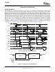
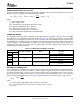
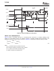
Figure 21. Grayscale PWM Cycle Timing Chart
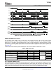
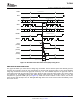
Figure 22 shows a cascading connection of n TLC5940 devices connected to a controller, building a basic
module of an LED display system. The maximum number of cascading TLC5940 devices depends on the
application system and is in the range of 40 devices. Equation 10 calculates the minimum frequency needed:
where:
f
(GSCLK)
: minimum frequency needed for GSCLK
f
(SCLK)
: minimum frequency needed for SCLK and SIN
f
(update)
: update rate of whole cascading system
n: number cascaded of TLC5940 device
20 Submit Documentation Feedback Copyright © 2004 – 2007, Texas Instruments Incorporated
Product Folder Link(s): TLC5940