
Data Sheet


www.ti.com
VPRG
XLAT
SIN
SCLK
SOUT
BLANK
GSCLK
OUT0
(current)
OUT1
(current)
OUT15
(current)
XERR
1 192
193
1
192
1
4096
GS1
MSB
GS1
LSB
GS1
MSB
GS2
MSB
GS2
LSB
GS2
MSB
SID1
MSB
SID1
MSB-1
SID1
LSB
- -
t +15xt +t
pd3 d pd2
t
pd3
t
d
15xt
d
t
pd2
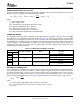
GSDataInputMode
1stGSDataInputCycle 2ndGSDataInputCycle
(1stGSDataOutputCycle)
t
suLOD
>tpd4+15xtd+tpd3
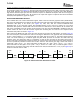
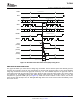
GRAYSCALE PWM OPERATION
TLC5940
SLVS515C – DECEMBER 2004 – REVISED OCTOBER 2007
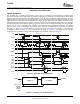
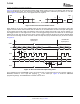
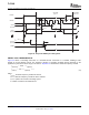
Figure 20. Readout Status Information Data (SID) Timing Chart
The grayscale PWM cycle starts with the falling edge of BLANK. The first GSCLK pulse after BLANK goes low
increases the grayscale counter by one and switches on all OUTn with grayscale value not zero. Each following
rising edge of GSCLK increases the grayscale counter by one. The TLC5940 compares the grayscale value of
each output OUTn with the grayscale counter value. All OUTn with grayscale values equal to the counter values
are switched off. A BLANK=H signal after 4096 GSCLK pulses resets the grayscale counter to zero and
completes the grayscale PWM cycle (see Figure 21 ). When the counter reaches a count of FFFh, the counter
stops counting and all outputs turn off. Pulling BLANK high before the counter reaches FFFh immediately resets
the counter to zero.
Copyright © 2004 – 2007, Texas Instruments Incorporated Submit Documentation Feedback 19
Product Folder Link(s): TLC5940