
Data Sheet


www.ti.com
VPRG
XLAT
SIN(a
)
SCLK
SOUT(b
)
BLANK
GSCLK
OUT0
(current)
OUT1
(current)
OUT15
(current)
XERR
1
192X2
DCb
MSB
DCa
LSB
DCb
MSB
1 384
385
1
384
385
1
1 4096 1
GSb1
MSB
GSa1
LSB
GSb1
MSB
GSb2
MSB
GSa2
LSB
GSb2
MSB
SIDb2
MSB
SIDb2
MSB
-1
SIDb1
MSB
SIDb1
MSB-1
SIDa1
LSB
GSb3
MSB
- --
192
96X2
ERROR INFORMATION OUTPUT
TEF: THERMAL ERROR FLAG
TLC5940
SLVS515C – DECEMBER 2004 – REVISED OCTOBER 2007
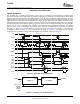
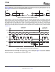
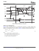
Figure 13. Timing Chart for Two Cascaded TLC5940 Devices
The open-drain output XERR is used to report both of the TLC5940 error flags, TEF and LOD. During normal
operating conditions, the internal transistor connected to the XERR pin is turned off. The voltage on XERR is
pulled up to V
CC
through an external pullup resistor. If TEF or LOD is detected, the internal transistor is turned
on, and XERR is pulled to GND. Since XERR is an open-drain output, multiple ICs can be OR'ed together and
pulled up to V
CC
with a single pullup resistor. This reduces the number of signals needed to report a system error
(see Figure 22 ).
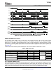
To differentiate LOD and TEF signal from XERR pin, LOD can be masked out with BLANK = HIGH.
Table 2. XERR Truth Table
ERROR CONDITION ERROR INFORMATION SIGNALS
TEMPERATURE OUTn VOLTAGE TEF LOD BLANK XERR
T
J
< T
(TEF)
Don't Care L X H
H
T
J
> T
(TEF)
Don't Care H X L
OUTn > V
(LED)
L L H
T
J
< T
(TEF)
OUTn < V
(LED)
L H L
L
OUTn > V
(LED)
H L L
T
J
> T
(TEF)
OUTn < V
(LED)
H H L
The TLC5940 provides a temperature error flag (TEF) circuit to indicate an overtemperature condition of the IC. If
the junction temperature exceeds the threshold temperature (160C typical), TEF becomes H and XERR pin goes
to low level. When the junction temperature becomes lower than the threshold temperature, TEF becomes L and
XERR pin becomes high impedance. TEF status can also be read out from the TLC5940 status register.
Copyright © 2004 – 2007, Texas Instruments Incorporated Submit Documentation Feedback 13
Product Folder Link(s): TLC5940