
Data Sheet

emitter and less from the other; hence one can determine reflector’s location based on the degree that the
light reception is not balanced.
The Z range is a measure of the direct illumination of both receivers. Accurate Z ranging is possible when
the reflector is positioned directly above the sensing element (or IR receiver).
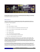
Output X and Z coordinate values are directly calculated by the sensor and presented to the serial link to
be included in the serial output. See section 6 for how the serial output is displayed in the demo
program. The actual calibrated Range (or Z) value may be calculated using an external serial program
that uses a sensor-output to actual range look-up table, to increase ranging accuracy. Such a table could
use a Linear-Spline calculation (for example) to improve the ranging resolution. The Range value
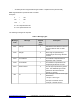
represents the actual distance as shown in the following geometric representation:
In the current design, the Range value output is limited between zero and +80 cm, designed for “arm’s-
length” use cases where low-power consumption is desired, and where the IR receiver senses little
reflective IR beyond the 80 cm range in this design. The limit is also imposed because the edge of the
sensor’s IR beam creates nonlinear effects when the reflector is partially within the beam directly ahead
of the sensor. Longer range sensors can operate at greater distances but require higher power to achieve
the IR reflectivity.
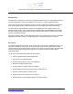
The reflecting surface can be any surface or object that has reflective properties varying from as little as
18% (i.e. the reflectance of a Kodak grey card) to 100% (i.e. or 95% for white paper).
UART Communication Protocol
Physical Interface:
The sensor reports periodically over an asynchronous serial interface (UART) using the following
configuration:
Baud-rate =115200 Data bits = 8 Parity = None No Handshaking
Data are reported only when a reflecting object is detected. The data refresh rate is approximately 50
samples per second.
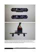
Communication Protocol:
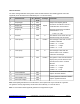
Data are reported as a binary frame with the following format:
Msg. Code
(0xF1 to 0xFF)
Data Payload
- Each message frame starts with a Message Code (1 byte) followed by a certain data payload
- Each message type is identified by a unique Message Code
- All message codes are larger than 0xF0.
andrew@xyzinteractive.com CONFIDENTIAL—XYZ Interactive Technologies Inc. Page 4