
Data Sheet
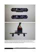

Note the labeled connections are shown here– it is important that the FTDI cable goes is connected to
the UART portion of the pin-out. I2C connections are for only the 3 pins on the right, as well as using
VCC and GND connections to power the sensor.
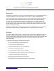
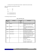
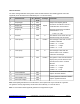
ZX Sensor Pin-out
The ZX sensor board contains two emitters and one receiver module, to determine the position of a
reflector in the Z X space, and is powered externally using a 4-pin standard 0.025-inch dip connector.
The following is the pin configuration:
1. Pin 1 : NC
2. pin 2 : Input voltage (5.0 volts DC)
3. Pin 3 : RX for connection to an external UART serial transmitter (TX) line
4. Pin 4 : TX for connection to an external UART serial receiver (RX) line
5. Pin 5 : GND for ground.
6. Pin 6 : GND for ground.
7. Pin 7 : DR (Data Ready) for the I2C interface.
8. Pin 8: CL (or the SCL) clock signal for the I2C interface.
9. Pin 9: DA (or SDA) data signal for the I2C Interface.
The input voltage to the board must be between 4.8 to 5.2 volts maximum, and the voltage is NOT
regulated on the sensor board itself. This was done purposefully to allow the user to apply any power
source from an external board supporting the serial I/O from the receiver board for further control
processing. Currently the RXD line does not support any serial data input to the sensor board. Note that
the sensor can function at lower voltages like 3.3 V but the lower emitter brightness will cause the sensor
to have reduced ranging performance.
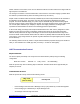
X is determined by measuring the differential illumination of the two optical elements
(emitter-receiver
pair). When the reflecting object (reflector) is precisely above the sensor, both optical elements are
equally illuminated, thus producing a zero brightness differential. By definition this position is referred to
as X origin, or X = 0. When the reflector is not centered, the receiver gets more reflected light from one
andrew@xyzinteractive.com CONFIDENTIAL—XYZ Interactive Technologies Inc. Page 3