
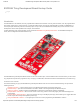
ESP8266 Thing Developpment Board w/ Headers Introduction

1/23/2018 ESP8266 Thing Development Board Hookup Guide - learn.sparkfun.com
https://learn.sparkfun.com/tutorials/esp8266-thing-development-board-hookup-guide/all 4/24
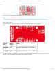
TX GPIO7, TX1 ESP8266 UART1 data output.
RX GPIO8, RX1 ESP8266 UART1 data input.
5V USB supply output. If USB is connected, this pin will
supply about 4.8V.
NC Not connected to anything.
GND Ground (0V).
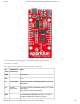
The top portion of this header breaks out the ESP8266’s I C interface, a popular interface for a variety of sensors including motion
sensor, light sensor, digital-to-analog converter, or OLED display, I C is often the protocol of choice.
If you need the extra I/O, instead of I C, the SDA and SCL pins can be used as GPIO 2 and 14 respectively. The SCL pin also
serves as the clock (SCLK) for the ESP8266’s SPI interface.
The lower part of the header breaks out one of the ESP8266’s serial UARTs. This serial port is used to program the thing, so be
careful using it for other tasks.
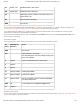
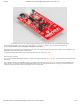
General I/O Header
The rest of the power, control, and I/O pins are broken out on the other side of the board. They are:
Pin
Label
ESP8266 I/O
Function
Notes
GND Ground (0V).
VIN USB connected: ~5V output
Can alternatively be used as a voltage supply input
to the 3.3V regulator.
5 GPIO5 This pin is also tied to the on-board LED.
0 GPIO0
4 GPIO4
13 GPIO13, MOSI Hardware SPI MOSI
12 GPIO12, MISO Hardware SPI MISO
16 GPIO16, XPD Can be connected to reset to wake the ESP8266
from deep sleep mode.
ADC A0 A 10-bit ADC with a maximum voltage of 1V.
15 GPIO15
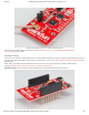
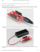
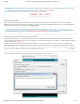
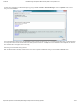
External Power Supply
If your project requires a power source other than USB, the Thing Dev Board includes footprints for a 2-pin JST, 2-pin 3.5mm screw
terminal, or a simple 0.1"-pitch 2-pin header.
2
2
2