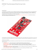
/23/2018 ESP8266 Thing Development Board Hookup Guide - learn.sparkfun.com ESP8266 Thing Development Board Hookup Guide ≡ Pages Introduction The ESP8266 is a cost-effective, and very capable WiFi-enabled microcontroller. Like any microcontroller, it can be programmed to blink LEDs, trigger relays, monitor sensors, or automate coffee makers, and with an integrated WiFi controller, the ESP8266 is a one-stop shop for almost any Internet-connected project.
1/23/2018 ESP8266 Thing Development Board Hookup Guide - learn.sparkfun.com Required Materials Beyond the ESP8266 Thing Development Board itself, all you should need to get started is a micro-B USB Cable, which will deliver power the board and set up our USB programming interface. Depending on how you want to use the board, you may also want to add male headers, female headers, or hedge your bets with 10pin stackable headers.
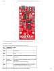
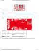
1/23/2018 ESP8266 Thing Development Board Hookup Guide - learn.sparkfun.com This section provides a quick overview of the Thing Dev Board’s main components. Serial and I2C Header The header on the left provides an interface for serial, I2C, and power: Pin Label ESP8266 I/O Function(s) Notes GND Ground (0V). 3V3 3.3V 2 GPIO2, SDA Can either be used as ESP8266 GPIO2 or I2C serial data (SDA). 14 GPIO14, SCL, SCLK Can either be used as ESP8266 GPIO14 or I2C serial clock (SCL).
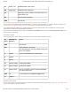
1/23/2018 ESP8266 Thing Development Board Hookup Guide - learn.sparkfun.com TX GPIO7, TX1 ESP8266 UART1 data output. RX GPIO8, RX1 ESP8266 UART1 data input. 5V USB supply output. If USB is connected, this pin will supply about 4.8V. NC Not connected to anything. GND Ground (0V).
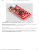
1/23/2018 ESP8266 Thing Development Board Hookup Guide - learn.sparkfun.com You can supply anywhere between 3.3V and 6V into these inputs to power the board. Note: Unlike the original ESP8266 Thing, the ESP8266 Thing Development Board does not have a built-in LiPo charger. A LiPo battery can be connected into a populated JST connector, but you'll need to add some extra circuitry to charge it.
1/23/2018 ESP8266 Thing Development Board Hookup Guide - learn.sparkfun.com The SLEEP_EN jumper set: enables using and waking up from deep sleep mode, but disables programming. To use the jumper solder a 2-pin male header and slide a 2-pin jumper on and off. This is a through-hole jumper only, because you’ll need to remove the jumper to program the ESP2866. The PWR-LED jumper allows you to disable the power LED.
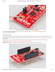
1/23/2018 ESP8266 Thing Development Board Hookup Guide - learn.sparkfun.com Antenna-select jumper set to U.FL, and an external attached. Then attach a U.FL WiFi antenna of your choice. Our adhesive antenna or a U.FL-to-RP-SMA adapter/2.4GHz Duck Antenna combo are good options. Hardware Setup To use any of the Thing Dev Board’s GPIO pins, you’ll need to solder something to the board.
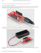
1/23/2018 ESP8266 Thing Development Board Hookup Guide - learn.sparkfun.com And, of course, wire can be soldered to any of the pins that have a long way to connect to something. Powering the Thing Development Board The easiest way to power the Thing Dev Board is by connecting a USB cable to the micro-B USB jack. The other end of the USB cable can be connected to your computer or a USB wall wart.
1/23/2018 ESP8266 Thing Development Board Hookup Guide - learn.sparkfun.com Driver Install: If you've never used an FTDI device, you may need to install drivers on your computer before you can program the ESP8266. For help with that, follow along with our How to Install FTDI Drivers tutorial. We have installation directions documented for all major operating systems: WINDOWS MAC LINUX Setting Up Arduino There are a variety of development environments that can be equipped to program the ESP8266.
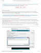
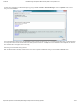
1/23/2018 ESP8266 Thing Development Board Hookup Guide - learn.sparkfun.com Hit OK. Then navigate to the Board Manager by going to Tools > Boards > Boards Manager. Look for esp8266. Click on that entry, then select Install. The board definitions and tools for the ESP8266 include a whole new set of gcc, g++, and other reasonably large, compiled binaries, so it may take a few minutes to download and install (the archived file is ~110MB).
1/23/2018 ESP8266 Thing Development Board Hookup Guide - learn.sparkfun.com Then select your FTDI’s port number under the Tools > Port menu. Upload Blink To verify that everything works, try uploading the old standard: Blink. But instead of blinking pin 13, toggle pin 5, which is attached to the onboard LED.
1/23/2018 ESP8266 Thing Development Board Hookup Guide - learn.sparkfun.
1/23/2018 ESP8266 Thing Development Board Hookup Guide - learn.sparkfun.com This faster upload speed can be slightly less reliable, but will save you loads of time! There are still some bugs to be fleshed out of the esptool, sometimes it may take a couple tries to successfully upload a sketch. If you’re still not having any luck uploading, try turning the board on then off, or unplug then replug the USB cable. If you still have trouble, get in touch with our amazing tech support team.
1/23/2018 ESP8266 Thing Development Board Hookup Guide - learn.sparkfun.com WiFiServer server(80); After uploading, find a device on the same WiFi network, and point it to one of these locations (the links below will only work if your device is on the same network): thing.local/read – Read the status of the ADC and the digital status of pin 12. thing.local/led/0 – Turn the LED on pin 5 off. thing.local/led/1 – Turn the LED on pin 5 on.
1/23/2018 ESP8266 Thing Development Board Hookup Guide - learn.sparkfun.com The sketch sets the network’s password to “sparkfun”. After connecting to your ESP8266’s AP network, load up a browser and point it to 192.168.4.1/read (unfortunately, mDNS doesn’t work in AP mode). The Thing Dev Board should serve up a web page showing you its ADC and digital pin 12 readings: After that, give 192.168.4.1/led/0 and 192.168.4.1/led/1 a try.
1/23/2018 ESP8266 Thing Development Board Hookup Guide - learn.sparkfun.com You’ll also need to install the Blynk Arduino Library, which helps generate the firmware running on your ESP8266. Download the latest release from Blynk’s GitHub repo, and follow along with the directions there to install the required libraries. DOWNLOAD AND INSTALL THE BLYNK ARDUINO LIBRARY Create a Blynk Project Next, click the “Create New Project” in the app to create a new Blynk app.
1/23/2018 ESP8266 Thing Development Board Hookup Guide - learn.sparkfun.com The Auth Token is very important – you’ll need to stick it into your ESP8266’s firmware. For now, copy it down or use the “E-mail” button to send it to yourself. Add Widgets to the Project Then you’ll be presented with a blank new project. To open the widget box, click in the project window to open. https://learn.sparkfun.
1/23/2018 ESP8266 Thing Development Board Hookup Guide - learn.sparkfun.com Add a Button, then click on it to change its settings. Buttons can toggle outputs on the ESP8266. Set the button’s output to gp5, which is tied to an LED on the Thing Dev Board. You may also want to change the action to “Switch.” https://learn.sparkfun.
1/23/2018 ESP8266 Thing Development Board Hookup Guide - learn.sparkfun.com Upload the Blynk Firmware Now that your Blynk project is set up, open Arduino and navigate to the ESP8266_Standalone example in the File > Examples > Blynk > BoardsAndShieldsmenu. https://learn.sparkfun.
1/23/2018 ESP8266 Thing Development Board Hookup Guide - learn.sparkfun.com Before uploading, make sure to paste your authoriazation token into the auth[] variable. Also make sure to load your WiFi network settings into the Blynk.begin(auth, "ssid", "pass") function. Then upload! Run the Project After the app has uploaded, open the serial monitor, setting the baud rate to 9600. Wait for the “Ready (ping: xms).” message. https://learn.sparkfun.
1/23/2018 ESP8266 Thing Development Board Hookup Guide - learn.sparkfun.com Then click the “Run” button in the top right corner of the Blynk app. Press the button and watch the LED! Then add more widgets to the project. They should immediately work on the ESP8266 without uploading any new firmware. https://learn.sparkfun.
1/23/2018 ESP8266 Thing Development Board Hookup Guide - learn.sparkfun.com You can add analog output sliders, digital input monitors, and analog input gauges. Using the ESP8266 in Arduino If you’ve used Arduino in the past, there will be some new programming schemes to get used to in ESP8266 land. Here are a few of the most common gotchyas. For a more comprehensive reference, check out the ESP8266 Arduino Reference page.
1/23/2018 ESP8266 Thing Development Board Hookup Guide - learn.sparkfun.com There’s only one analog input pin, labeled ADC. To read the ADC pin, make a function call to analogRead(A0) . Remember that this pin has a weird maximum voltage of 1V – you’ll get a 10-bit value (0-1023) proportional to a voltage between 0 and 1V. All digital pins are also capable of PWM “analog” output. Use analogWrite([pin], [value]) with a value between 0 and 1023 to dim LEDs with a 1kHz PWM signal.
1/23/2018 ESP8266 Thing Development Board Hookup Guide - learn.sparkfun.com A lot of the core Arduino libraries have been re-written to work for the ESP8266, including: Wire – The ESP8266 should work with any I2C sensor you can throw at it – just use the same Wire API calls you’re used to. There are a few differences: Pin definition: The ESP2866 doesn’t actually have any hardware I2C pins – those labeled on the Thing are the default, but you can actually use any two pins as SDA and SCL. Calling Wire.