
Data Sheet

MMA8452Q
Sensors
Freescale Semiconductor, Inc. 35
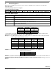
0x28: PULSE_WIND Register (Read/Write)
The bits WIND7 through WIND0 define the maximum interval of time that can elapse after the end of the latency interval in which
the start of the second pulse event must be detected provided the device has been configured for double pulse detection. The
detected second pulse width must be shorter than the time limit constraints specified by the PULSE_TMLT register, but the end
of the double pulse need not finish within the time specified by the PULSE_WIND register.
The minimum time step for the pulse window is defined in Table 48 and Table 49. The maximum time is the time step at the ODR,
Oversampling mode and LPF Filter Option multiplied by 255.
0x28: PULSE_WIND Second Pulse Time Window Register
Bit
7
Bit
6
Bit
5
Bit
4
Bit
3
Bit
2
Bit
1
Bit
0
WIND7 WIND6 WIND5 WIND4 WIND3 WIND2 WIND1 WIND0
Table 47. PULSE_WIND Description
WIND[7:0]
Second Pulse Time Window. Default value: 0000_0000.
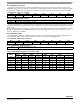
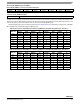
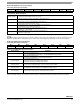
Table 48. Time Step for PULSE Detection Window @ ODR and Power Mode (Reg 0x0F) Pulse_LPF_EN = 1
ODR (Hz)
Max Time Range (s) Time Step (ms)
Normal LPLN HighRes LP Normal LPLN HighRes LP
800 0.638 0.638 0.638 0.638 2.5 2.5 2.5 2.5
400 1.276 1.276 1.276 1.276 5 5 5 5
200 2.56 2.56 1.276 2.56 10 10 5 10
100 5.1 5.1 1.276 5.1 20 20 5 20
50 10.2 10.2 1.276 10.2 40 40 5 40
12.5 10.2 40.8 1.276 40.8 40 160 5 160
6.25 10.2 40.8 1.276 81.6 40 160 5 320
1.56 10.2 40.8 1.276 81.6 40 160 5 320
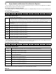
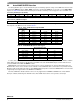
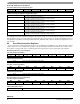
Table 49. Time Step for PULSE Detection Window @ ODR and Power Mode (Reg 0x0F) Pulse_LPF_EN = 0
ODR (Hz)
Max Time Range (s) Time Step (ms)
Normal LPLN HighRes LP Normal LPLN HighRes LP
800 0.318 0.318 0.318 0.318 1.25 1.25 1.25 1.25
400 0.318 0.318 0.318 0.638 1.25 1.25 1.25 2.5
200 0.638 0.638 0.318 1.276 2.5 2.5 1.25 5
100 1.276 1.276 0.318 2.56 5 5 1.25 10
50 2.56 2.56 0.318 5.1 10 10 1.25 20
12.5 2.56 10.2 0.318 20.4 10 40 1.25 80
6.25 2.56 10.2 0.318 20.4 10 40 1.25 80
1.56 2.56 10.2 0.318 20.4 10 40 1.25 80