
Data Sheet

MMA8452Q
Sensors
20 Freescale Semiconductor, Inc.
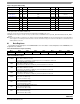
ZYXOW is set whenever a new acceleration data is produced before completing the retrieval of the previous set. This event
occurs when the content of at least one acceleration data register (i.e., OUT_X, OUT_Y, OUT_Z) has been overwritten. ZYXOW
is cleared when the high-bytes of the acceleration data (OUT_X_MSB, OUT_Y_MSB, OUT_Z_MSB) of all the active channels are
read.
ZOW is set whenever a new acceleration sample related to the Z-axis is generated before the retrieval of the previous sample.
When this occurs the previous sample is overwritten. ZOW is cleared anytime OUT_Z_MSB register is read.
YOW is set whenever a new acceleration sample related to the Y-axis is generated before the retrieval of the previous sample.
When this occurs the previous sample is overwritten. YOW is cleared anytime OUT_Y_MSB register is read.
XOW is set whenever a new acceleration sample related to the X-axis is generated before the retrieval of the previous sample.
When this occurs the previous sample is overwritten. XOW is cleared anytime OUT_X_MSB register is read.
ZYXDR signals that a new sample for any of the enabled channels is available. ZYXDR is cleared when the high-bytes of the
acceleration data (OUT_X_MSB, OUT_Y_MSB, OUT_Z_MSB) of all the enabled channels are read.
ZDR is set whenever a new acceleration sample related to the Z-axis is generated. ZDR is cleared anytime OUT_Z_MSB register
is read.
YDR is set whenever a new acceleration sample related to the Y-axis is generated. YDR is cleared anytime OUT_Y_MSB register
is read.
XDR is set whenever a new acceleration sample related to the X-axis is generated. XDR is cleared anytime OUT_X_MSB register
is read.
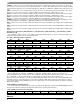
Data Registers: 0x01: OUT_X_MSB, 0x02: OUT_X_LSB, 0x03: OUT_Y_MSB, 0x04: OUT_Y_LSB, 0x05: OUT_Z_MSB,
0x06: OUT_Z_LSB
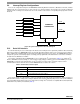
These registers contain the X-axis, Y-axis, and Z-axis 12-bit output sample data expressed as 2's complement numbers. The
sample data output registers store the current sample data.
OUT_X_MSB, OUT_X_LSB, OUT_Y_MSB, OUT_Y_LSB, OUT_Z_MSB, and OUT_Z_LSB are stored in the auto-
incrementing address range of 0x01 to 0x06 to reduce reading the status followed by 12-bit axis data to 7 bytes. If the F_READ
bit is set (0x2A bit 1), auto-increment will skip over LSB registers. This will shorten the data acquisition from
7 bytes to 4 bytes. The LSB registers can only be read immediately following the read access of the corresponding MSB register.
A random read access to the LSB registers is not possible. Reading the MSB register and then the LSB register in sequence
ensures that both bytes (LSB and MSB) belong to the same data sample, even if a new data sample arrives between reading the
MSB and the LSB byte.
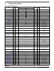
0x0B: SYSMOD System Mode Register
The system mode register indicates the current device operating mode. Applications using the Auto-SLEEP/WAKE mechanism
should use this register to synchronize the application with the device operating mode transitions.
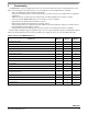
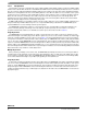
0x01: OUT_X_MSB: X_MSB Register (Read Only)
Bit 7 Bit 6 Bit 5 Bit 4 Bit 3 Bit 2 Bit 1 Bit 0
XD11 XD10 XD9 XD8 XD7 XD6 XD5 XD4
0x02: OUT_X_LSB: X_LSB Register (Read Only)
Bit 7 Bit 6 Bit 5 Bit 4 Bit 3 Bit 2 Bit 1 Bit 0
XD3XD2XD1XD00000
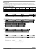
0x03: OUT_Y_MSB: Y_MSB Register (Read Only)
Bit 7 Bit 6 Bit 5 Bit 4 Bit 3 Bit 2 Bit 1 Bit 0
YD11 YD10 YD9 YD8 YD7 YD6 YD5 YD4
0x04: OUT_Y_LSB: Y_LSB Register (Read Only)
Bit 7 Bit 6 Bit 5 Bit 4 Bit 3 Bit 2 Bit 1 Bit 0
YD3YD2XD1XD00000
0x05: OUT_Z_MSB: Z_MSB Register (Read Only)
Bit 7 Bit 6 Bit 5 Bit 4 Bit 3 Bit 2 Bit 1 Bit 0
ZD11 ZD10 ZD9 ZD8 ZD7 ZD6 ZD5 ZD4
0x06: OUT_Z_LSB: Z_LSB Register (Read Only)
Bit 7 Bit 6 Bit 5 Bit 4 Bit 3 Bit 2 Bit 1 Bit 0
ZD3ZD2ZD1ZD0 0 0 0 0
0x0B: SYSMOD: System Mode Register (Read Only)
Bit
7
Bit
6
Bit
5
Bit
4
Bit
3
Bit
2
Bit
1
Bit
0
0 0 0 0 0 0 SYSMOD1 SYSMOD0