
Data Sheet

MMA8452Q
Sensors
10 Freescale Semiconductor, Inc.
4 Modes of Operation
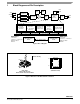
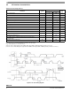
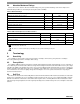
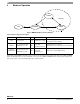
Figure 6. MMA8452Q Mode Transition Diagram
All register contents are preserved when transitioning from ACTIVE to STANDBY mode. Some registers are reset when
transitioning from STANDBY to ACTIVE. These are all noted in the device memory map register table. The SLEEP and WAKE
modes are ACTIVE modes. For more information on how to use the SLEEP and WAKE modes and how to transition between
these modes, please refer to the functionality section of this document.
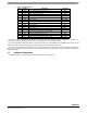
Table 7. Mode of Operation Description
Mode
I
2
C Bus State
VDD VDDIO Function Description
OFF
Powered Down
<1.8V
VDDIO Can be > VDD
The device is powered off. All analog and digital blocks
are shutdown. I
2
C bus inhibited.
STANDBY
I
2
C communication with
MMA8452Q is possible
ON
VDDIO = High
VDD = High
ACTIVE bit is cleared
Only digital blocks are enabled.
Analog subsystem is disabled. Internal clocks disabled.
ACTIVE
(WAKE/SLEEP)
I
2
C communication with
MMA8452Q is possible
ON
VDDIO = High
VDD = High
ACTIVE bit is set
All blocks are enabled (digital, analog).
SLEEP
WAKE
STANDBY
OFF
ACTIVE