
User Guide

1/16/2018 H3LIS331DL Accelerometer Breakout Hookup Guide - learn.sparkfun.com
https://learn.sparkfun.com/tutorials/h3lis331dl-accelerometer-breakout-hookup-guide?_ga=2.255828235.2084638943.1516049849-204410570.150963…
7/7
xl.setI2CAddr(0x19); // This MUST be called BEFORE .begin() so
// .begin() can communicate with the chip
xl.begin(LIS331::USE_I2C); // Selects the bus to be used and sets
// the power up bit on the accelerometer.
// Also zeroes out all accelerometer
// registers that are user writable.
SPI Mode Setup
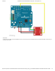
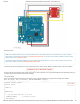
Here we have the first few lines of an SPI mode sketch. Again, order is important: pinMode() , SPI.begin() ,
and xl.setSPICSPin() functions must all be called before the xl.begin() function is called.
After this point, the code for either mode of operation is the same. Note that this example code includes only the second half of the
setup function, and if you’re copy/pasting from this example, you must copy the other half of the setup function from one of the
above code chunks.
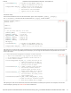
After placing the code into the Arduino IDE, select the board definition and COM port to upload. Once compiled, check out the
sensor readings by opening up a serial monitor set to 115200 baud.
COPY CODE
#include "SparkFun_LIS331.h"
#include <SPI.h>
LIS331 xl;
void setup()
{
// put your setup code here, to run once:
pinMode(9,INPUT); // Interrupt pin input
pinMode(10, OUTPUT); // CS for SPI
digitalWrite(10, HIGH); // Make CS high
pinMode(11, OUTPUT); // MOSI for SPI
pinMode(12, INPUT); // MISO for SPI
pinMode(13, OUTPUT); // SCK for SPI
SPI.begin();
xl.setSPICSPin(10); // This MUST be called BEFORE .begin() so
// .begin() can communicate with the chip
xl.begin(LIS331::USE_SPI); // Selects the bus to be used and sets
COPY CODE
// This next section configures an interrupt. It will cause pin
// INT1 on the accelerometer to go high when the absolute value
// of the reading on the Z-axis exceeds a certain level for a
// certain number of samples.
xl.intSrcConfig(LIS331::INT_SRC, 1); // Select the source of the
// signal which appears on pin INT1. In
// this case, we want the corresponding
// interrupt's status to appear.
xl.setIntDuration(50, 1); // Number of samples a value must meet
// the interrupt condition before an
// interrupt signal is issued. At the
// default rate of 50Hz, this is one sec.
xl.setIntThreshold(2, 1); // Threshold for an interrupt. This is
// not actual counts, but rather, actual
// counts divided by 16.
xl.enableInterrupt(LIS331::Z_AXIS, LIS331::TRIG_ON_HIGH, 1, true);
// Enable the interrupt. Parameters indicate
// which axis to sample, when to trigger