
Data Sheet

Register description H3LIS331DL
26/38 DocID023111 Rev 3
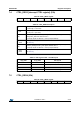
The BOOT bit is used to refresh the content of the internal registers stored in the Flash
memory block. At device power-up, the content of the Flash memory block is transferred to
the internal registers related to trimming functions in order to permit correct operation of the
device itself. If for any reason the content of the trimming registers is changed, it is sufficient
to use this bit to restore the correct values. When the BOOT bit is set to ‘1’, the content of
the internal Flash is copied inside the corresponding internal registers and it is used to
calibrate the device. These values are factory trimmed and they are different for every
accelerometer. They permit correct operation of the device and normally they do not have to
be changed. At the end of the boot process the BOOT bit is set again to ‘0’.
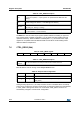
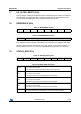
HPCF[1:0]. These bits are used to configure the high-pass filter cutoff frequency f
t
which is
given by:
The equation can be simplified to the following approximated equation:
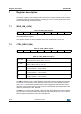
HPen1
High-pass filter enabled for interrupt 1 source. Default value: 0
(0: filter bypassed; 1: filter enabled)
HPCF1,
HPCF0
High-pass filter cutoff frequency configuration. Default value: 00
(00: HPc=8; 01: HPc=16; 10: HPc=32; 11: HPc=64)
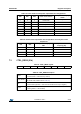
Table 23. High-pass filter mode configuration
HPM1 HPM0 High-pass filter mode
00Normal mode (reset reading HP_RESET_FILTER)
01Reference signal for filtering
10Normal mode (reset reading HP_RESET_FILTER)
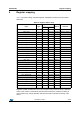
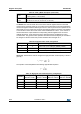
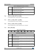
Table 24. High-pass filter cutoff frequency configuration
HPcoeff2,1
f
t
[Hz]
Data rate = 50 Hz
f
t
[Hz]
Data rate = 100 Hz
f
t
[Hz]
Data rate = 400 Hz
f
t
[Hz]
Data rate = 1000 Hz
00 1 2 8 20
01 0.5 1 4 10
10 0.25 0.5 2 5
11 0.125 0.25 1 2.5
Table 22. CTRL_REG2 description (continued)
f
t
1
1
HPc
----------- -–
f
s
2
------ln=
f
t
f
s
6HPc
-------------------=