
Data Sheet

TMP35/TMP36/TMP37
Rev. F | Page 10 of 20
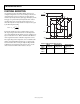
BASIC TEMPERATURE SENSOR CONNECTIONS
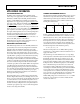
Figure 24 illustrates the basic circuit configuration for the
TMP3x family of temperature sensors. The table in Figure 24
shows the pin assignments of the temperature sensors for the
three package types. For the SOT-23, Pin 3 is labeled NC, as are
Pin 2, Pin 3, Pin 6, and Pin 7 on the SOIC_N package. It is
recommended that no electrical connections be made to these
pins. If the shutdown feature is not needed on the SOT-23 or
on the SOIC_N package, the
SHUTDOWN
pin should be
connected to +V
S
.
2.7V < +
V
S
< 5.5
V
V
OUT
0.1µF
+V
S
GND
PACKAGE
+V
S
GND
V
OUT
SOIC_N 8 4 1 5
SOT-23 2 5 1 4
TO-92 1 3 2 NA
PIN ASSIGNMENTS
S
HUTDOWN
TMP3x
00337-022
SHUTDOWN
Figure 24. Basic Temperature Sensor Circuit Configuration
Note the 0.1 μF bypass capacitor on the input. This capacitor
should be a ceramic type, have very short leads (surface-mount
is preferable), and be located as close as possible in physical
proximity to the temperature sensor supply pin. Because these
temperature sensors operate on very little supply current and
may be exposed to very hostile electrical environments, it is
important to minimize the effects of radio frequency interference
(RFI) on these devices. The effect of RFI on these temperature
sensors specifically and on analog ICs in general is manifested as
abnormal dc shifts in the output voltage due to the rectification
of the high frequency ambient noise by the IC. When the
devices are operated in the presence of high frequency radiated
or conducted noise, a large value tantalum capacitor (±2.2 μF)
placed across the 0.1 μF ceramic capacitor may offer additional
noise immunity.
FAHRENHEIT THERMOMETERS
Although the TMP3x temperature sensors are centigrade
temperature sensors, a few components can be used to convert
the output voltage and transfer characteristics to directly read
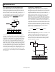
Fahrenheit temperatures. Figure 25 shows an example of a
simple Fahrenheit thermometer using either the TMP35 or the
TMP37. Using the TMP35, this circuit can be used to sense
temperatures from 41°F to 257°F with an output transfer
characteristic of 1 mV/°F; using the TMP37, this circuit can be
used to sense temperatures from 41°F to 212°F with an output
transfer characteristic of 2 mV/°F. This particular approach
does not lend itself to the TMP36 because of its inherent 0.5 V
output offset. The circuit is constructed with an AD589, a 1.23 V
voltage reference, and four resistors whose values for each sensor
are shown in the table in Figure 25. The scaling of the output
resistance levels ensures minimum output loading on the temp-
erature sensors. A generalized expression for the transfer
equation of the circuit is given by
()
()
AD589
R4R3
R3
TMP35
R2R1
R1
V
OUT
⎟
⎟
⎠
⎞
⎜
⎜
⎝
⎛
+
+
⎟
⎟
⎠
⎞
⎜
⎜
⎝
⎛
+
=
where:
TMP35 is the output voltage of the TMP35 or the TMP37 at the
measurement temperature, T
M
.
AD589 is the output voltage of the reference, that is, 1.23 V.
The output voltage of this circuit is not referenced to the
circuit’s common ground. If this output voltage were applied
directly to the input of an ADC, the ADC common ground
should be adjusted accordingly.
SENSOR
TCV
OUT
R1 (kΩ)
TMP35
1mV/°F 45.3 10 10 374
TMP37 2mV/°F 45.3 10 10 182
R2 (kΩ)R3 (kΩ)R4 (kΩ)
TMP35/
TMP37
GND
R1
R2
R3
R4
AD589
1.23V
0.1µF
V
OUT
+
V
S
V
OUT
+V
S
–
+
00337-023
Figure 25. TMP35/TMP37 Fahrenheit Thermometers