
Manual
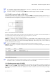
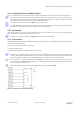
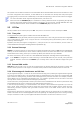
Table Of Contents
- Preface
- Contents
- 1 Hardware description
- 2 Design-in
- 2.1 Power management
- 2.2 Interfaces
- 2.3 I/O Pins
- 2.4 Real-Time Clock (RTC)
- 2.5 RF input
- 2.6 Safe Boot Mode (SAFEBOOT_N)
- 2.7 System Reset (RESET_N)
- 2.8 Pin description
- 2.9 Typical schematic
- 2.10 Design-in checklist
- 2.11 Layout design-in checklist
- 2.12 Layout
- 2.13 EOS/ESD/EMI precautions
- 3 Product handling & soldering
- 4 Product testing
- Appendix
- A Component selection
- B Glossary
- Related documents
- Revision history
- Contact

ZOE-M8 series - Hardware Integration Manual
UBX-16030136 - R07 Production Information Design-in
Page 9 of 32
2.2.2 Display Data Channel (DDC) interface
An I
2
C compatible Display Data Channel (DDC) interface is available for serial communication with a host CPU.
The SCL and SDA pins have internal pull-up resistors sufficient for most applications. However, depending on
the speed of the host and the load on the DDC lines additional external pull-up resistors might be necessary.
For the speed and clock frequency, see the ZOE-M8 Data Sheet [1].
To make use of DDC interface, the D_SEL pin must be left open.
The ZOE-M8 GNSS SiPs DDC interface provides serial communication with u-blox cellular modules. See the
specification of the applicable cellular module to confirm compatibility.
2.2.3 SPI interface
Use the SPI interface to provide a serial communication with a host CPU. If the SPI interface is used, UART and
DDC are deactivated, because they share the same pins.
To make use of the SPI interface, the D_SEL pin must be connected to GND.
2.2.1 SQI interface
An external SQI (Serial Quad Interface) flash memory can be connected to the ZOE-M8 GNSS SiPs. The SQI interface
provides the following options:
• Store the current configuration permanently
• Save data logging results
• Hold AssistNow Offline and AssistNow Autonomous data
In addition, the ZOE-M8 GNSS SiPs can make use of a dedicated flash firmware with an external SQI flash
memory. The flash memory with these SiPs can be use to run firmware out of flash and to update the firmware
as well. Running the firmware from the SQI flash requires a minimum SQI flash size of 8 Mbit.
The voltage level of the SQI interface follows the VCC level. Therefore, the SQI flash must be supplied with
the same voltage as VCC of the ZOE-M8 SiPs. It is recommended to place a decoupling capacitor (C4) close
to the supply pin of the SQI flash.
Make sure that the SQI flash supply range matches the voltage supplied at VCC.
Figure 2: Connecting an external SQI flash memory