
Manual
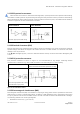
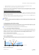
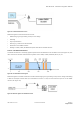
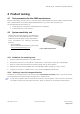
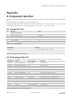
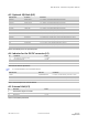
Table Of Contents
- Preface
- Contents
- 1 Hardware description
- 2 Design-in
- 2.1 Power management
- 2.2 Interfaces
- 2.3 I/O Pins
- 2.4 Real-Time Clock (RTC)
- 2.5 RF input
- 2.6 Safe Boot Mode (SAFEBOOT_N)
- 2.7 System Reset (RESET_N)
- 2.8 Pin description
- 2.9 Typical schematic
- 2.10 Design-in checklist
- 2.11 Layout design-in checklist
- 2.12 Layout
- 2.13 EOS/ESD/EMI precautions
- 3 Product handling & soldering
- 4 Product testing
- Appendix
- A Component selection
- B Glossary
- Related documents
- Revision history
- Contact

ZOE-M8 series - Hardware Integration Manual
UBX-16030136 - R07 Production Information Design-in
Page 23 of 32
Figure 17: In-band interference sources
Measures against in-band interference include:
• Maintaining a good grounding concept in the design
• Shielding
• Layout optimization
• Filtering e.g. resistors and ferrite beads
• Placement of the GNSS antenna
• Adding a CDMA, GSM, WCDMA band-pass filter before handset antenna
2.13.6.4 Out-band interference
Out-band interference is caused by signal frequencies that are different from the GNSS carrier (see Figure 18). The
main sources are wireless communication systems such as GSM, CDMA, WCDMA, Wi-Fi, BT, etc.
Figure 18: Out-band interference signals
Measures against out-band interference include maintaining a good grounding concept in the design and adding
a SAW or band-pass ceramic filter (as recommend in section 2.13.6) into the antenna input line to the GNSS
receiver (see Figure 19).
Figure 19: Measures against out-band interference