
Manual
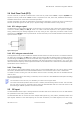
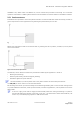
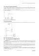
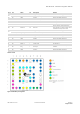
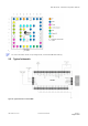
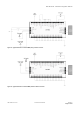
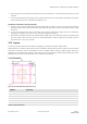
Table Of Contents
- Preface
- Contents
- 1 Hardware description
- 2 Design-in
- 2.1 Power management
- 2.2 Interfaces
- 2.3 I/O Pins
- 2.4 Real-Time Clock (RTC)
- 2.5 RF input
- 2.6 Safe Boot Mode (SAFEBOOT_N)
- 2.7 System Reset (RESET_N)
- 2.8 Pin description
- 2.9 Typical schematic
- 2.10 Design-in checklist
- 2.11 Layout design-in checklist
- 2.12 Layout
- 2.13 EOS/ESD/EMI precautions
- 3 Product handling & soldering
- 4 Product testing
- Appendix
- A Component selection
- B Glossary
- Related documents
- Revision history
- Contact

ZOE-M8 series - Hardware Integration Manual
UBX-16030136 - R07 Production Information Design-in
Page 18 of 32
2.10 Design-in checklist
2.10.1 General considerations
Check power supply requirements and schematic:
Is the power supply voltage within the specified range? See how to connect power in section 2.1 and
section 2.9.
Compare the peak current consumption of ZOE-M8 GNSS SiPs with the specification of your power supply.
GNSS receivers require a stable power supply. Avoid series resistance in your power supply line (the line to
VCC) to minimize the voltage ripple on VCC.
Backup battery
For achieving a minimal Time-To-First-Fix (TTFF) after a power down (warm starts, hot starts), make sure to
connect a backup battery to V_BCKP, and use an RTC. If not used, make sure V_BCKP is connected to
neighbor pin G9.
Antenna/ RF input
Make sure the antenna is not placed close to noisy parts of the circuitry and not facing noisy parts. (e.g. micro-
controller, display, etc.)
Make sure your RF front end is chosen according your design, see section 2.5.
For more information dealing with interference issues, see the GPS Antenna Application Note [3]
2.10.2 Schematic design-in for ZOE-M8 GNSS SiPs
For a minimal design with the ZOE-M8 GNSS SiPs, the following functions and pins need to be considered:
• Connect the power supply to VCC and V_BCKP.
• If you use DC/DC converter on the ZOE-M8Q, ensure the external inductor and capacitor are in place in
between V_DCDC_OUT and V_CORE.
• Ensure an optimal ground connection to all ground pins of the ZOE-M8 GNSS SiPs.
• Choose the required serial communication interfaces (UART, SPI or DDC) and connect the appropriate pins to
your application.
• If you need hot or warm start in your application, connect a Backup Battery to V_BCKP and add an RTC circuit.
2.11 Layout design-in checklist
Follow this checklist for the layout design to get an optimal GNSS performance.
Layout optimizations (see Section 2.12)
Is the ZOE-M8 GNSS SiP placed according to the recommendation in section 2.12.3?
Is the grounding concept optimal?
Are all the GND pins well connected with GND?
Has the 50 Ohm line from the antenna to the SiP (micro strip / coplanar waveguide) been kept as short as
possible?
Assure low serial resistance in VCC power supply line (choose a line width > 400 µm).
Assure all VCC pins are well connected with the power supply line.
Keep the power supply line as short as possible.
If DC/DC is used on the ZOE-M8Q, ensure the inductor and capacitor are connected close to the ZOE-M8Q
V_CORE and V_DCDC_OUT pins and the capacitor has a good GND connection.
Design a GND guard ring around the optional RTC crystal lines and GND below the RTC circuit.