
Manual
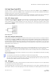
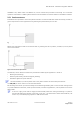
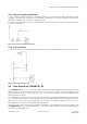
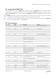
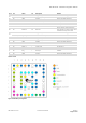
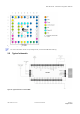
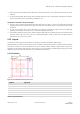
Table Of Contents
- Preface
- Contents
- 1 Hardware description
- 2 Design-in
- 2.1 Power management
- 2.2 Interfaces
- 2.3 I/O Pins
- 2.4 Real-Time Clock (RTC)
- 2.5 RF input
- 2.6 Safe Boot Mode (SAFEBOOT_N)
- 2.7 System Reset (RESET_N)
- 2.8 Pin description
- 2.9 Typical schematic
- 2.10 Design-in checklist
- 2.11 Layout design-in checklist
- 2.12 Layout
- 2.13 EOS/ESD/EMI precautions
- 3 Product handling & soldering
- 4 Product testing
- Appendix
- A Component selection
- B Glossary
- Related documents
- Revision history
- Contact

ZOE-M8 series - Hardware Integration Manual
UBX-16030136 - R07 Production Information Design-in
Page 15 of 32
Pin # SiP Name I/O Description Remark
G1
ZOE-M8G VCC I Supply voltage Clean and stable supply needed
ZOE-M8Q V_CORE I Core Supply voltage Connect to VCC if DCDC not used
G3 All GND Ground Ensure good GND connection
G4 All PIO13 / EXTINT I External interrupt Leave open if not used.
G5 All Reserved I/O Reserved Do not connect. Must be left open!
G6 All GND Ground Ensure good GND connection
G7 All GND Ground Ensure good GND connection
G9 All Reserved I/O Reserved
Do not connect. Must be left open!
Only exception is V_BCKP, which can be
connected to this pin if not used.
H1
ZOE-M8G VCC I Supply voltage Clean and stable supply needed
ZOE-M8Q V_DCDC_OUT O DC/DC converter output Connect to VCC if DCDC not used
H9 All V_BCKP I Backup supply
J1 All VCC I Supply voltage Clean and stable supply needed
J2 All VCC I Supply voltage Clean and stable supply needed
J3 All GND Ground Ensure good GND connection
J4 All RXD/SPI MOSI I Serial interface See section 2.2.
J5 All TXD/SPI MISO O Serial interface See section 2.2.
J6 All RESET_N I System reset See section 2.7.
J7 All RTC_I I RTC Input
Connect to GND if no RTC Crystal
attached.
J8 All RTC_O O RTC Output Leave open if no RTC Crystal attached.
J9 All GND Ground Ensure good GND connection
Table 3: Pinout
Figure 8: ZOE-M8G pin assignment