ZOE-M8 series Ultra-small u-blox M8 SiP modules Hardware Integration Manual Abstract This document describes the hardware features and specifications of the u-blox ZOE-M8G and ZOE-M8Q GNSS SiP (System in Package) modules. www.u-blox.
ZOE-M8 series - Hardware Integration Manual Document Information Title ZOE-M8 series Subtitle Ultra-small u-blox M8 SiP modules Document type Hardware Integration Manual Document number UBX-16030136 Revision and date R07 Document status Production Information 14-Mar-2018 Document status explanation Objective Specification Document contains target values. Revised and supplementary data will be published later. Advance Information Document contains data based on early testing.
ZOE-M8 series - Hardware Integration Manual Preface u-blox Technical Documentation As part of our commitment to customer support, u-blox maintains an extensive volume of technical documentation for our products. In addition to our product-specific technical data sheets, the following manuals are available to assist u-blox customers in product design and development.
ZOE-M8 series - Hardware Integration Manual Contents Preface ................................................................................................................................ 3 Contents.............................................................................................................................. 4 1 Hardware description .................................................................................................. 6 1.1 2 Overview ........................................
ZOE-M8 series - Hardware Integration Manual 3 4 2.13.1 2.13.2 Electrostatic Discharge (ESD)........................................................................................................ 20 ESD protection measures ............................................................................................................. 21 2.13.3 Electrical Overstress (EOS) ............................................................................................................ 21 2.13.4 2.13.
ZOE-M8 series - Hardware Integration Manual 1 Hardware description 1.1 Overview u-blox ZOE-M8 standard precision GNSS SiP (System in Package) modules feature the high performance u-blox M8 GNSS engine. ZOE-M8’s ultra-miniature form factor integrates a complete GNSS receiver including SAW filter, LNA and TCXO. The ZOE-M8 SiPs are targeted for applications that require a small size without compromising the performance.
ZOE-M8 series - Hardware Integration Manual Do not add any series resistance greater than 0.1 Ω to the V_CORE supply as it will generate input voltage noise due to the dynamic current conditions. If a DC/DC converter is not used, supply V_CORE with the same supply as used for the VCC. 2.1.3 DC/DC converter (only on ZOE-M8Q) ZOE-M8Q comes with a built-in DC/DC converter to supply V_CORE, thus enabling significant power savings. For more information, see the ZOE-M8 Data Sheet [1].
ZOE-M8 series - Hardware Integration Manual The GNSS satellite ephemeris data is typically valid for up to 4 hours. To enable hot starts, ensure that the battery or capacitor at V_BCKP is able to supply the backup current for at least 4 hours. For warm starts or when using the AssistNow Autonomous, the V_BCKP source must be able to supply current for up to a few days. If no backup supply is available, V_BCKP can be connected to the reserved neighbor pin G9.
ZOE-M8 series - Hardware Integration Manual 2.2.2 Display Data Channel (DDC) interface 2 An I C compatible Display Data Channel (DDC) interface is available for serial communication with a host CPU. The SCL and SDA pins have internal pull-up resistors sufficient for most applications. However, depending on the speed of the host and the load on the DDC lines additional external pull-up resistors might be necessary. For the speed and clock frequency, see the ZOE-M8 Data Sheet [1].
ZOE-M8 series - Hardware Integration Manual An SQI flash size of 8 Mbit is sufficient to save AssistNow Offline and AssistNow Autonomous information as well as current configuration data. However, for ZOE-M8 SiPs to run Firmware from the SQI flash and provide space for logging results, a minimum size of 8 Mbit may not be sufficient depending on the amount of data to be logged. For more information about supported SQI flash devices, see section A.3.
ZOE-M8 series - Hardware Integration Manual 2.4 Real-Time Clock (RTC) The use of the RTC is optional to maintain time in the event of power failure at VCC. It requires V_BCKP to be supplied in case of power failure at VCC. The RTC is required for hot start, warm start, AssistNow Autonomous, AssistNow Offline and in some Power Save Mode operations. The time information can either be generated by connecting an external RTC crystal to the SiP, by connecting an external 32.
ZOE-M8 series - Hardware Integration Manual GLONASS L1OF, Galileo E1B/C and BeiDou B1) can be received and processed concurrently. This concurrent operation is extended to 3 GNSS systems whenever GPS and Galileo are used in addition to GLONASS or BeiDou. 2.5.1 Passive antenna ZOE-M8 SiPs are optimized to work with passive antennas. The internal SAW filter inside followed by an LNA is a good compromise for most applications from jamming and performance point of view.
ZOE-M8 series - Hardware Integration Manual 2.5.2 Improved jamming immunity If strong out-band jammers are close to the GNSS antenna (e.g. a GSM antenna), GNSS performance can be degraded or the maximum input power of the ZOE-M8 GNSS SiPs RF-input can be exceeded. In that case, the SAW filter (F1) must be put in front of the external LNA (U1). It should be noted that the insertion loss of the SAW filter (F1) directly affects the system noise figure and hence the system performance.
ZOE-M8 series - Hardware Integration Manual 2.7 System Reset (RESET_N) The ZOE-M8 GNSS SiPs provide a RESET_N pin to reset the system. The RESET_N is an input-only with internal pull-up resistor. It must be at low level for at least 10 ms to make sure RESET_N is detected. It is used to reset the system. Leave RESET_N open for normal operation. The RESET_N complies with the VCC level and can be actively driven high. RESET_N should be only used in critical situations to recover the system.
ZOE-M8 series - Hardware Integration Manual Pin # SiP Name I/O Description Remark G1 ZOE-M8G ZOE-M8Q VCC V_CORE I I Supply voltage Core Supply voltage Clean and stable supply needed Connect to VCC if DCDC not used G3 All GND Ground Ensure good GND connection G4 G5 All All PIO13 / EXTINT Reserved External interrupt Reserved Leave open if not used. Do not connect.
ZOE-M8 series - Hardware Integration Manual Figure 9: ZOE-M8Q pin assignment For more information about the pin assignments, see the ZOE-M8 Data Sheet [1]. 2.
ZOE-M8 series - Hardware Integration Manual Figure 11: Typical schematic for the ZOE-M8Q using a DC/DC converter Figure 12: Typical schematic for the ZOE-M8Q without a DC/DC converter UBX-16030136 - R07 Production Information Design-in Page 17 of 32
ZOE-M8 series - Hardware Integration Manual 2.10 Design-in checklist 2.10.1 General considerations Check power supply requirements and schematic: Is the power supply voltage within the specified range? See how to connect power in section 2.1 and section 2.9. Compare the peak current consumption of ZOE-M8 GNSS SiPs with the specification of your power supply. GNSS receivers require a stable power supply.
ZOE-M8 series - Hardware Integration Manual Add a ground plane underneath the GNSS SiP to reduce interference. This is especially important for the RF input line. For improved shielding, add as many vias as possible around the micro strip/coplanar waveguide, around the serial communication lines, underneath the GNSS SiP, etc.
ZOE-M8 series - Hardware Integration Manual 2.12.2 Paste mask The paste mask shall be same as the copper pads with a paste thickness of 80 µm. These are recommendations only and not specifications. The exact geometry, distances, stencil thicknesses and solder paste volumes must be adapted to the specific production processes (e.g. soldering etc.) of the customer. 2.12.3 Placement A very important factor in achieving maximum GNSS performance is the placement of the receiver on the PCB.
ZOE-M8 series - Hardware Integration Manual 2.13.2 ESD protection measures GNSS receivers are sensitive to Electrostatic Discharge (ESD). Special precautions are required when handling. Most defects caused by ESD can be prevented by following strict ESD protection rules for production and handling. When implementing passive antenna patches or external antenna connection points, then additional ESD measures as shown in Figure 14 can also avoid failures in the field.
ZOE-M8 series - Hardware Integration Manual • Weakly shielded lines on PCB (e.g. on top or bottom layer and especially at the border of a PCB) • Weak GND concept (e.g. small and/or long ground line connections) EMI protection measures are recommended when RF emitting devices are near the GNSS receiver. To minimize the effect of EMI, a robust grounding concept is essential. To achieve electromagnetic robustness, follow the standard EMI suppression techniques. http://www.murata.
ZOE-M8 series - Hardware Integration Manual Figure 17: In-band interference sources Measures against in-band interference include: • Maintaining a good grounding concept in the design • Shielding • Layout optimization • Filtering e.g. resistors and ferrite beads • Placement of the GNSS antenna • Adding a CDMA, GSM, WCDMA band-pass filter before handset antenna 2.13.6.
ZOE-M8 series - Hardware Integration Manual 3 Product handling & soldering 3.1 Packaging, shipping, storage and moisture preconditioning For information pertaining to reels and tapes, Moisture Sensitivity levels (MSD), shipment and storage information, as well as drying for preconditioning see the ZOE-M8 Data Sheet [1]. 3.2 ESD handling precautions ESD prevention is based on establishing an Electrostatic Protective Area (EPA). The EPA can be a small working station or a large manufacturing area.
ZOE-M8 series - Hardware Integration Manual 3.4 Soldering 3.4.1 Soldering paste Use of "No Clean" soldering paste is strongly recommended, as it does not require cleaning after the soldering process has taken place. The paste-mask geometry for applying soldering paste should meet the recommendations given in section 2.12.2. 3.4.2 Reflow soldering Preheat/ Soak Temperature min. Preheat/ Soak Temperature max.
ZOE-M8 series - Hardware Integration Manual 4 Product testing 4.1 Test parameters for the OEM manufacturer Because of the testing done by u-blox, it is obvious that an OEM manufacturer doesn’t need to repeat firmware tests or measurements of the GNSS parameters/characteristics (e.g. TTFF) in their production test. An OEM manufacturer should focus on: • Overall sensitivity of the device (including antenna, if applicable) • Communication to a host controller 4.
ZOE-M8 series - Hardware Integration Manual Appendix A Component selection This section provides information about components that are critical for the performance of the ZOE-M8 GNSS SiPs. Recommended parts are selected on a data sheet basis only. Temperature range specifications need only be as wide as required by a particular application. For the purpose of this document, specifications for industrial temperature range (-40 C … +85 C) are provided. A.1 External RTC (Y1) ID Parameter Value 1 1.
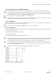
ZOE-M8 series - Hardware Integration Manual A.3 Optional SQI flash (U3) Manufacturer Order No. Comments Macronix MX25L3233F 3 V, 32 Mbit, several package/temperature options Macronix Macronix MX25V8035F MX25V1635F 3 V, 8 Mbit, several package/temperature options 3 V, 16 Mbit, several package/temperature options Macronix Spansion MX25R1635FxxxH1 S25FL116K 1.
ZOE-M8 series - Hardware Integration Manual Manufacturer Order No. Comments Maxim MAX2659ELT+ Low noise figure, up to 10 dBm RF input power JRC New Japan Radio NXP NJG1143UA2 BGU8006 Low noise figure, up to 15 dBm RF input power Low noise figure, very small package size (WL-CSP) Infineon BGA524N6 Low noise figure, small package size Table 13: Recommend parts list for external LNA A.6 RF ESD protection diode Manufacturer Order No. ON Semiconductor ESD9R3.
ZOE-M8 series - Hardware Integration Manual B Glossary Abbreviation Definition ANSI American National Standards Institute BeiDou Chinese satellite navigation system CDMA Code Division Multiple Access EMI Electromagnetic interference EOS Electrical Overstress EPA Electrostatic Protective Area ESD Electrostatic discharge Galileo European navigation system GLONASS Russian satellite system GND Ground GNSS Global Navigation Satellite System GPS Global Positioning System GSM Global Sys
ZOE-M8 series - Hardware Integration Manual Related documents [1] ZOE-M8 Data Sheet, Document No. UBX-16008094 [2] u-blox 8 / u-blox M8 Receiver Description Including Protocol Specification (Public version), Document No. UBX-13003221 [3] GPS Antenna Application Note, Document No. GPS-X-08014 [4] [5] GPS Compendium, Document No. GPS-X-02007 GPS Implementation and Aiding Features in u-blox wireless modules, Document No. GSM.
ZOE-M8 series - Hardware Integration Manual Contact For complete contact information, visit us at www.u-blox.com u-blox Offices North, Central and South America u-blox America, Inc. Phone: E-mail: +1 703 483 3180 info_us@u-blox.com Regional Office West Coast: Phone: +1 408 573 3640 E-mail: info_us@u-blox.com Technical Support: Phone: E-mail: Headquarters Europe, Middle East, Africa Asia, Australia, Pacific u-blox AG Phone: E-mail: Support: Phone: E-mail: Support: +41 44 722 74 44 info@u-blox.