
Data Sheet

October 2017 BNO080 Datasheet 1000-3927
www.hillcrestlabs.com © 2017 Hillcrest Laboratories, Inc. All rights reserved. 48 / 57
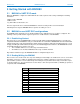
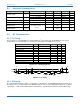
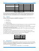
Figure 6-9: Host interrupt timing - SPI mode
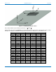
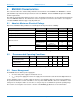
Parameter
Symbol
Min
Typ
Max
Unit
I
2
C address recognize to H_INTN dessert
tclid
10
µs
BNO080 wakeup from wake signal assert
twk
150
µs
H_CSN to H_INTN de-assert
tcsid
800
ns
H_INTN assert to UART transmission
tiatx
7.7
µs
H_INTN deassertion to H_INTN reassert
tidia
1
µs
Figure 6-10: H_INTN timing
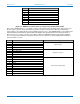
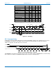
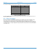
In UART-SHTP mode the interrupt is asserted prior to the UART transmission. It is assumed that the host can
always accept data over its UART. The interrupt is asserted approx. 7.7 µs prior to the first bit of UART
transmission:
Figure 6-11: Host interrupt timing - UART-SHTP mode
The interrupt will be de-asserted prior to the termination of the UART transmission.
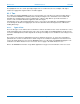
6.6 Mechanical Characteristics
The sensors within the BNO080 are specified by Bosch Sensortec. The mechanical and electrical details of the
raw sensors are specified in the BMF055 datasheet [5].
The SH-2 software within the BNO080 configures the accelerometer for a range of +/- 8g and the gyroscope with
a range of +/- 2000 ˚/s.
6.7 Performance Characteristics
The SH-2 software within the BNO080 calibrates and interprets the raw sensor data received from the gyroscope,
accelerometer and magnetometer. By fusing the data from all three sensors the BNO080 can provide an estimate
of the orientation of the device, the applied acceleration (i.e. gravity is removed from the accelerometer signal)
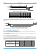
and an estimate of gravity. Figure 6-12 captures the performance of the BNO080 when using an external clock or
crystal.
Composite Sensor
Calibration
Measurement
Performance Metric
Value
Rotation Vector
Nominal
Dynamic
Rotation Error
3.5°
Static
Rotation Error
2.0°
Gaming Rotation Vector
Nominal
Dynamic
Non-heading Error
2.5°
Static
Non-heading Error
1.5°
Dynamic
Heading Drift
0.5°/min
PS0/wake
H_INTN
H_CSN
twk
tcsid
Start
Stop
D7D6D5D4D3D2D1D0
H_INTN
UART_TX
tiatx
tidia