
Data Sheet

October 2017 BNO080 Datasheet 1000-3927
www.hillcrestlabs.com © 2017 Hillcrest Laboratories, Inc. All rights reserved. 39 / 57
3.1.6 Recommended Settings
Note that by default the accelerometer and magnetometer calibration are enabled for all interface modes except
UART-RVC. In UART-RVC mode planar-ZGO calibration is enabled.
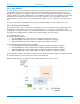
For general applications that require motion tracking in a relatively stable magnetic field it is recommended to use
9-axis sensor fusion outputs (Rotation Vector – see section 2.2.4) from the BNO080. If the device to which the
BNO080 is attached provides sufficient tremor then the gyroscope calibration can be enabled. However the user
should verify performance with their specific motion profile.
If the application requires an orientation estimate in an unstable magnetic field, the Game Rotation Vector may be
more useful.
For virtual reality applications, stability and smoothness of head tracking is important. During application use
dynamic calibration of the magnetometer can result in undesirable motion artifacts such as jumps as the BNO080
attempts to compensate for magnetic field distortions. It is therefore recommended to use the Game Rotation
Vector (see section 2.2.2) or gyro rotation Vector (see section 2.2.6 and 2.2.7 ) and only enable the calibration of
the accelerometer.
For RVC applications it is generally expected that the UART-RVC mode be used and in this case planar ZGO will
be enabled by default. If the user has a similar application but requires higher rate outputs then alternate
interfaces can be used. The planar accelerometer calibration can be enabled by the user.
3.2 Calibration Steps
For best motion tracking performance, it is recommended to calibrate the BNO080. Since each MEMS sensor part
has different individual characteristics, each device using the BNO080 must be calibrated individually.
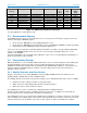
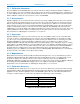
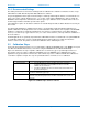
Figure 3-2 summarizes the steps required to calibrate the accelerometer, gyroscope and magnetometer. For
more details on the procedure to calibrate the BNO080, refer to the BNO080 Sensor Calibration Procedure
application note [7]. Note that in normal use the device will be exposed to conditions that will allow calibration to
occur with no explicit user input. The steps are provided below if a user wants to force a calibration.
Sensor
Calibration Procedure
Accelerometer
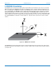
• For 3D calibration the device should be moved into 4-6 unique
orientation and held in each orientation for about 1 second to
calibrate the accelerometer
• For planar calibration the device should be rotated around it Z-axis
by at least 180 degrees
Gyroscope
Device should be set down on a stationary surface for approximately 2-3
seconds to calibrate the gyroscope
Magnetometer
Device should be rotated about 180° and back to the beginning position in
each axis (roll, pitch and yaw). Device should be rotated about 2 seconds on
each axis.
Figure 3-2: Calibration procedure for sensors