
Data Sheet

October 2017 BNO080 Datasheet 1000-3927
www.hillcrestlabs.com © 2017 Hillcrest Laboratories, Inc. All rights reserved. 29 / 57
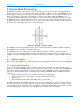
In this example, the first sensor report should be timestamped as occurring at T-12ms and the second at T –
10.3ms (T - 12ms + 1.7ms).
1.5 Bootloader
The BNO080 provides a bootloader function to allow firmware upgrades to be applied. During reset or power-on
sequence, the bootloader first checks the status of the BOOTN pin. If the pin is pulled low during reset or power-
on, the BNO080 will enter the bootloader mode. If the BOOTN pin is pulled high, then the bootloader starts the
application.
The bootloader uses the host interface as configured by the PS0/1 pins (see Figure 1-5). If I
2
C is selected the
bootloader has an I
2
C address of either 0x28 or 0x29 (SA0 provides the lowest address bit).
After the BNO080 enters the bootloader mode, it waits for the size of the application code from the host. The
application to be written to flash is split into a number of frames. The application in flash is updated by writing
these frames to the BNO080 and reading a status back to verify the write was successful.
Reference code (on the host microcontroller) for using the bootloader to perform Device Firmware Upgrade (DFU)
is available upon request.