
Data Sheet

October 2017 BNO080 Datasheet 1000-3927
www.hillcrestlabs.com © 2017 Hillcrest Laboratories, Inc. All rights reserved. 19 / 57
6. After reset the PS0/WAKE signal is used as a ‘wake’ signal taking the BNO080 out of sleep if the host wants
to initiate communication with the BNO080.
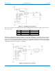
7. The BNO080 supports environmental sensors (e.g. pressure sensors, ambient light sensors) on a secondary
I
2
C interface. This interface should be pulled up via resistors regardless of the presence of the external
sensor as the SW polls for sensors at reset.
1.3.4.1 SPI Operation
SPI is a 4-wire synchronous serial protocol. SPI provides a full duplex communication path and has a
master/slave relationship. The master provides the clock for all transactions. Multiple slave devices can exist on a
SPI interface by the use of a chip select signal. The BNO080 is the slave in all communications.
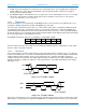
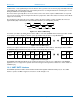
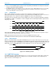
SPI allows for two clock polarities and clock edge sampling. These options are typically called CPOL and CPHA.
The BNO080 uses CPOL = 1 and CPHA = 1. In this configuration the clock idles high and data is captured on the
rising edge of the clock:
Figure 1-21: BNO080 SPI signaling
SPI transmits data MSB first and is byte oriented (i.e. all data is passed in 8-bit segments). Any number of bytes
can be transferred in a single transaction (chip select assertion).
MISO is the data transferred from the slave to the master and MOSI from master to slave.
The BNO080 uses Hillcrest’s SHTP protocol to communicate. More details are available at [2].
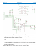
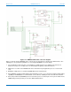
1.3.4.2 Wake operation
When the host want to initiate contact with the BNO080 it may be necessary to wake the processor from a sleep
mode. To enable this function the BNO080 uses the PS0/wake pin. The pin is active low and should be driven low
to initiate the wake procedure. The BNO080 will respond by asserting the interrupt line at which point the host can
initiate SPI accesses. The BNO080 will de-assert the interrupt line as soon as the chip select is detected.
Figure 1-22: SPI Wake operation
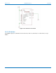
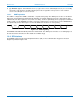
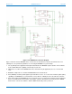
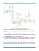
1.3.5 UART-RVC interface
The BNO080 provides a simplified UART interface for use on robot vacuum cleaners (RVC). When configured in
this mode the BNO080 simply transmits heading and sensor information at 100Hz over the UART TX pin. A
typical connection is shown in Figure 1-23
D7 D6 D5 D4 D2 D1 D0D3
D7 D6 D5 D4 D2 D1 D0D3
CS
CLK
MISO
MOSI
PS0/wake
H_INTN
H_CSN