
Data Sheet

October 2017 BNO080 Datasheet 1000-3927
www.hillcrestlabs.com © 2017 Hillcrest Laboratories, Inc. All rights reserved. 15 / 57
endian format – least-significant byte first. The master device generates the clock. Every byte transmitted must be
acknowledged. An acknowledgement is generated by the device receiving the data and is formed by the receiver
driving the SDA line low during the ninth bit.
The master device generally drives the clock. However, if the slave device requires additional time to respond it
can force the clock low, only releasing the line when it is prepared to deliver more data. The master device MUST
support clock stretching.
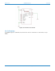
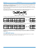
The first byte presented after the start condition contains the device address and the read/write bit. The least-
significant bit (LSB) of this first byte is the read/write indication (‘0’ corresponding to write)
Figure 1-15: Device addressing
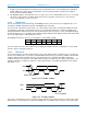
For a write cycle data is provided after the device address. The slave (BNO080 in this instance) provides an ACK
for every byte received. A typical I
2
C write cycle is provided below (S=start, P=stop, AD=Address).
Figure 1-16: I
2
C write cycle
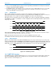
A read cycle requires that the device must first be selected with its device address. Following the device address
the BNO080 will provide data. Every byte should be acknowledged by the master:
Figure 1-17: I
2
C read cycle
The BNO080 uses Hillcrest’s SHTP (Sensor Hub Transport Protocol) protocol to communicate. The BNO080
application does not support the repeated start method for typical I
2
C register based interfaces. More details are
available in [2].
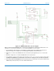
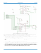
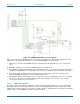
1.3.3 UART-SHTP interface
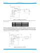
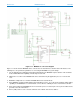
The BNO080 provides a UART communication interface that supports Hillcrest’s SHTP protocol. The UART
interface operates at 3Mb/s. A typical connection is shown in Figure 1-18
SDA
SCL
A6-0
R/W
ACK
S 1-7 8 9
START
Address
R/W ACK
S AD+W
ACK
DATA
ACK
Master
Slave
DATA
ACK
PDATA
ACK
DATA
ACK
S AD+R
ACK
ACK
DATA
Master
Slave
NAK
DATA
PACK
DATA
ACK
DATA