BNO080 Data Sheet The BNO080 is a System in Package (SiP) that integrates a triaxial accelerometer, triaxial gyroscope, magnetometer and a 32-bit ARM® Cortex™-M0+ microcontroller running Hillcrest’s SH-2 firmware. The SH-2 includes the MotionEngine™ software, which provides sophisticated signal processing algorithms to process sensor data and provide precise real-time 3D orientation, heading, calibrated acceleration and calibrated angular velocity, as well as more advanced contextual outputs.
October 2017 BNO080 Datasheet 1000-3927 Table of Contents LIST OF FIGURES .......................................................................................................................... 4 1 FUNCTIONAL OVERVIEW ................................................................................................ 6 1.1 Reference Design Configurations ................................................................................... 7 1.1.1 Standalone Sensor Hub Solution in Mobile Devices ...........
October 2017 BNO080 Datasheet 1000-3927 3.1.6 Recommended Settings ............................................................................................. 39 3.2 Calibration Steps .......................................................................................................... 39 4 BNO080 ORIENTATION .................................................................................................. 40 4.1.1 Tare 42 5 GETTING STARTED WITH BNO080 ...........................................
October 2017 BNO080 Datasheet 1000-3927 List of Figures Figure 1-1: BNO080 block diagram ...........................................................................................................................6 Figure 1-2: BNO080 in a mobile device.....................................................................................................................7 Figure 1-3: Virtual reality head tracker ..................................................................................................
October 2017 BNO080 Datasheet 1000-3927 Figure 6-8: Host interrupt timing – I2C mode .......................................................................................................... 47 Figure 6-9: Host interrupt timing - SPI mode .......................................................................................................... 48 Figure 6-10: H_INTN timing ....................................................................................................................................
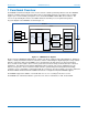
October 2017 BNO080 Datasheet 1000-3927 1 Functional Overview The BNO080 is manufactured by Bosch Sensortec and runs software provided by Hillcrest Labs. The BNO080 integrates a triaxial 12-bit accelerometer with a range of ±8g, triaxial 16-bit gyroscope with a range of ±2000 degrees per second, a triaxial geomagnetic sensor, and a 32-bit ARM® Cortex™-M0+ microcontroller. The sensors are provided by Bosch Sensortec GmbH and the Cortex M0+ processor by Atmel Corporation.
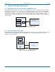
October 2017 1.1 BNO080 Datasheet 1000-3927 Reference Design Configurations 1.1.1 Standalone Sensor Hub Solution in Mobile Devices The BNO080 can be integrated as a co-processor in a mobile device such as a smartphone, tablet or ultrabook. This means the host processor can offload the sensor management and processing functions to the BNO080.
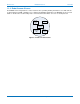
October 2017 BNO080 Datasheet 1000-3927 1.1.4 Robot Vacuum Cleaner The BNO080 can be integrated into a robot vacuum cleaner, providing heading information to fuse with cameras to allow navigation (SLAM – Simultaneous Localization and Mapping application). The BNO080 can also provide details on the tilt of the vacuum and by virtue of the included accelerometer can serve as a bump detector.
October 2017 1.3 BNO080 Datasheet 1000-3927 BNO080 Connectivity The BNO080 can support connections to a host microcontroller through various serial interfaces: • I2C interface • UART interface • SPI interface • UART-RVC interface – a simplified UART interface for Robot Vacuum Cleaners In addition, the BNO080 includes a bootloader to allow for firmware upgrades. The bootloader can support I 2C, SPI or UART. Access to the bootloader is achieved by setting BOOTN to 0.
October 2017 BNO080 Datasheet 1000-3927 1.3.1 Pin Descriptions Figure 1-6 describes the function of each pin.
October 2017 BNO080 Datasheet 1000-3927 Figure 1-7: 32.768kHz crystal connection Clock source selection is done during startup using the CLKSEL0 and CLKSEL1 pins. Figure 1-8 shows how to select each source. Source Crystal External Internal CLKSEL0 0 or unconnected 1 1 CLKSEL1 Connected to crystal 1 0 or unconnected Figure 1-8: Clock Source Selection CLKSEL0 is configured with an internal pulldown at startup.
October 2017 BNO080 Datasheet 1000-3927 Figure 1-10: Internal clock selection 1.3.2 I2C interface The BNO080 supports a standard Fast mode I2C interface and can communicate over this interface at up to 400kb/s. www.hillcrestlabs.com © 2017 Hillcrest Laboratories, Inc. All rights reserved.
October 2017 BNO080 Datasheet 1000-3927 Figure 1-11: BNO080 I2C connection diagram Figure 1-11 shows how the BNO080 can be connected to an external microcontroller via the I2C interface. The following notes are provided as guidelines for connecting the BNO080 in a system design. 1. The H_INTN pin is the application interrupt line that indicates the BNO080 requires attention. This should be tied to a GPIO with wake capability. The interrupt is active low. 2.
October 2017 BNO080 Datasheet 1000-3927 7. Pullup resistors (R1 and R2) are needed on the I2C communication lines – Pin 19 (HOST_SCL) and Pin 20 (HOST_SDA). These values may vary depending on the board design and bus capacitance, but typical values are between 2KΩ and 4KΩ. 8. The BNO080 supports environmental sensors (e.g. pressure sensors, ambient light sensors) on a secondary I2C interface.
October 2017 BNO080 Datasheet 1000-3927 endian format – least-significant byte first. The master device generates the clock. Every byte transmitted must be acknowledged. An acknowledgement is generated by the device receiving the data and is formed by the receiver driving the SDA line low during the ninth bit. The master device generally drives the clock.
October 2017 BNO080 Datasheet 1000-3927 Figure 1-18: BNO080 UART-SHTP connection diagram Figure 1-18 shows how the BNO080 can be connected to an external microcontroller via a UART interface. The following notes are provided as guidelines for connecting the BNO080 in a system design. 1. The H_INTN pin is driven low prior to the initial byte of UART transmission. It will deassert and reassert between messages. It is used by the host to timestamp the beginning of data transmission. 2.
October 2017 BNO080 Datasheet 1000-3927 6. The BNO080 supports environmental sensors (e.g. pressure sensors, ambient light sensors) on a secondary I2C interface. This interface should be pulled up via resistors regardless of the presence of the external sensor as the SW polls for sensors at reset. 1.3.3.1 UART operation The UART is configured for 3Mkb/s, 8 data bits, 1 stop bit and no parity. The UART protocol relies on an idle line being ‘high’.
October 2017 BNO080 Datasheet 1000-3927 Figure 1-20: BNO080 SPI connection diagram Figure 1-20 shows how the BNO080 can be connected to an external microcontroller via a SPI interface. The following notes are provided as guidelines for connecting the BNO080 in a system design. 1. The H_INTN pin is the application interrupt line that indicates the BNO080 requires attention. This should be tied to a GPIO with wake capability. The interrupt is active low. 2.
October 2017 BNO080 Datasheet 1000-3927 6. After reset the PS0/WAKE signal is used as a ‘wake’ signal taking the BNO080 out of sleep if the host wants to initiate communication with the BNO080. 7. The BNO080 supports environmental sensors (e.g. pressure sensors, ambient light sensors) on a secondary I2C interface. This interface should be pulled up via resistors regardless of the presence of the external sensor as the SW polls for sensors at reset. 1.3.4.
October 2017 BNO080 Datasheet 1000-3927 Figure 1-23: BNO080 UART-RVC connection diagram Figure 1-23 shows how the BNO080 can be connected to an external microcontroller via a UART interface. The following notes are provided as guidelines for connecting the BNO080 in a system design. 1. NRST is the reset line for the BNO080 and can be either driven by the application processor or the board reset. 2. BOOTN is sampled at reset. If low the BNO080 will enter bootloader mode. 3.
October 2017 BNO080 Datasheet Start D0 D1 D2 D3 1000-3927 D4 D5 D6 D7 Z-axis accel Reserved Stop Figure 1-24: UART signaling 1.3.5.2 UART-RVC protocol The BNO080 transmits the following data at a rate of 100Hz.
October 2017 BNO080 Datasheet Byte 0 1 2 3 1000-3927 Field Length LSB Length MSB Channel SeqNum Figure 1-26: SHTP Header Length Bit 15 of the length field is used to indicate if a transfer is a continuation of a previous transfer. Bits 14:0 are used to indicate the total number of bytes in the cargo plus header, which may be spread over multiple messages. The bytes in the header field are counted as part of the length.
October 2017 BNO080 Datasheet SHTP Channel 1 (executable) Use 1000-3927 Direction 0 – reserved 1 – reset 2 – on 3 – sleep 4-255 – reserved 0 – reserved 1 – reset complete 2-255 – reserved Write Read Figure 1-27: SHTP executable commands and response The use of the ‘on’ and ‘sleep’ commands provides support when the host is entering and exiting sleep. When the ‘sleep’ command is issued all sensors that are configured as always on or wake (see 1.4.5.
October 2017 BNO080 Datasheet Byte 10 11 12 13 14 15 1000-3927 Description SW Build Number … SW Build Number MSB SW Version Patch LSB SW Version Patch MSB Reserved Reserved Figure 1-29: Product ID Response The list of currently supported commands/configurations is: SHTP Channel 2 (SH-2 control) 2 (SH-2 control) 2 (SH-2 control) 2 (SH-2 control) 2 (SH-2 control) 2 (SH-2 control) 2 (SH-2 control) 2 (SH-2 control) 2 (SH-2 control) 2 (SH-2 control) 2 (SH-2 control) 2 (SH-2 control) Direction Host to BNO Ho
October 2017 BNO080 Datasheet Record ID 0xD7D7 0x4B4B 0x39AF 0x4D20 0x1AC9 0x39B1 0x4DA2 0xD401 0xD402 0xED85 0x74B4 0xD403 0xA1A2 1000-3927 Description Maximum fusion period Serial number Environmental sensor - Pressure calibration Environmental sensor - Temperature calibration Environmental sensor - Humidity calibration Environmental sensor - Ambient light calibration Environmental sensor - Proximity calibration ALS Calibration Proximity Sensor Calibration Stability detector configuration User record M
October 2017 BNO080 Datasheet LSB Byte 1 Byte 2 MSB 1000-3927 – ME version – MH version – SH version – 0x00 Range The range of the sensor. The format is unsigned fixed point. The units and Q point are the same as those used in the sensor’s input report. Resolution The resolution of the sensor. The format is unsigned fixed point. The units and Q point are the same as those used in the sensor’s input report. Power The power used by the sensor in mA when operating. The format is unsigned fixed point.
October 2017 BNO080 Datasheet Byte 0 1 2 3 4 5 6 7 8 9 10 11 12 13 14 15 16 1000-3927 Description Report ID = 0xFD Feature Report ID Feature flags Change sensitivity [absolute | relative] LSB Change sensitivity [absolute | relative] MSB Report Interval LSB Report Interval Report Interval Report Interval MSB Batch Interval LSB Batch Interval Batch Interval Batch Interval MSB Sensor-specific configuration word LSB Sensor-specific configuration word Sensor-specific configuration word Sensor-specific configu
October 2017 BNO080 Datasheet Byte 6 7 8 9 1000-3927 Description Gyroscope calibrated Axis Y LSB Gyroscope calibrated Axis Y MSB Gyroscope calibrated Axis Z LSB Gyroscope calibrated Axis Z MSB Figure 1-34: Calibrated gyroscope input report The sequence number is a monotonically increasing value that is used to check for dropped samples. The status byte is broken into two fields: Bits 1:0 – indicate the status of a sensor.
October 2017 BNO080 Datasheet 1000-3927 In this example, the first sensor report should be timestamped as occurring at T-12ms and the second at T – 10.3ms (T - 12ms + 1.7ms). 1.5 Bootloader The BNO080 provides a bootloader function to allow firmware upgrades to be applied. During reset or power-on sequence, the bootloader first checks the status of the BOOTN pin. If the pin is pulled low during reset or poweron, the BNO080 will enter the bootloader mode.
October 2017 BNO080 Datasheet 1000-3927 2 Sensor Data Processing The BNO080 analyzes the data from the 3-axis accelerometer, 3-axis gyroscope and 3-axis magnetometer. It manages the various sensors, reads data, and provides a number of outputs to the host. The BNO080 processes motion relative to a frame of reference. It has no knowledge of the orientation of sensors within the device and must be configured to conform to the desired frame of reference of the device.
October 2017 BNO080 Datasheet 1000-3927 2.1.2 Angular Velocity Outputs The 3-axis gyroscope measures the angular velocity of the device. The angular velocity is reported as rotations around the X, Y, Z axes as depicted in Figure 2-1. A positive value is reported for counter-clockwise rotations. BNO080 calibrates this data to improve the measurement and provides the following outputs: • Calibrated gyroscope (rad/s). The angular velocity of the device • Uncalibrated gyroscope (rad/s).
October 2017 BNO080 Datasheet 1000-3927 yaw due to the characteristics of gyroscopes, but this is seen as preferable for this output versus a corrected output. 2.2.3 AR/VR Stabilized Game Rotation vector While the magnetometer is removed from the calculation of the game rotation vector, the accelerometer itself can create a potential correction in the rotation vector produced (i.e. the estimate of gravity changes).
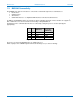
October 2017 BNO080 Datasheet Prediction Time (s) Alpha Beta 0.028 0.005 0.01 0.02 0.03 0.04 0.05 0.06 0.3030725439091 0.3643672983581 0.3222569517214 0.2905555274225 0.3084584610521 0.3396316005051 0.3548447957314 0.4091677424529 0.1132958963849 0.0931655637068 0.0945467654507 0.1018361851286 0.1160861868509 0.1237361273333 0.1224432975403 0.1250943899234 Gamma 0.0027762197131 0.0025557744608 0.0022830845312 0.0023953721024 0.0028497585549 0.0030844488660 0.0032236047505 0.
October 2017 BNO080 Datasheet 1000-3927 The FRS record that configures the stability classifier is encoded in the MotionEngine power management and stability classifier FRS record. The FRS record provides a stable threshold and a duration threshold. The data from the gyroscope must be below the stable threshold for the duration threshold period for Stable to be declared. The default values are 1 rad/s and 3s respectively.
October 2017 BNO080 Datasheet 1000-3927 2.4.4 Step Counter The step counter uses the step detector to detect and count steps. It provides a more accurate indication of steps taken than the step detector. It provides increased accuracy by evaluating the data around each step event, possibly reclassifying previous samples as either steps or non-steps, depending upon the patterns perceived. It outputs a 16-bit step count.
October 2017 BNO080 Datasheet 1000-3927 2.4.6 Significant Motion Detector The significant motion detector was introduced by Google in Android 4.3 (API level 18). The definition is that an event should be raised when a user has created motion that implies they have changed location. The typical usecase is that the sensor be low power (as it can run while the phone is asleep) and that it alerts the main processing element of the device when a change in location is likely.
October 2017 BNO080 Datasheet 1000-3927 3 Calibration and Interpretation The BNO080 interprets the data from its sensors to model the device’s motion and ultimately determine the device’s orientation and classify the motion of the device. The accuracy of this model is dependent on the quality of the data provided by the sensors. All sensors exhibit slight imperfections. These imperfections generally appear as errors in offset and scale.
October 2017 BNO080 Datasheet 1000-3927 3.1.1 Calibration Command The SH-2 firmware in the BNO080 allows a host microcontroller to enable or disable the dynamic calibration of the accelerometer, gyroscope and magnetometer. Refer to the SH-2 Reference Manual [1] for the command used to control calibration of each sensor. The command allows the host to control when calibration is performed. Note that the calibration settings do not persist across resets of the BNO080. 3.1.
October 2017 BNO080 Datasheet 1000-3927 3.1.6 Recommended Settings Note that by default the accelerometer and magnetometer calibration are enabled for all interface modes except UART-RVC. In UART-RVC mode planar-ZGO calibration is enabled. For general applications that require motion tracking in a relatively stable magnetic field it is recommended to use 9-axis sensor fusion outputs (Rotation Vector – see section 2.2.4) from the BNO080.
October 2017 BNO080 Datasheet 1000-3927 4 BNO080 Orientation The BNO080 can be mounted in an arbitrary manner that facilitates the manufacture of the device it is included within. The outputs of the BNO080 must however be aligned to a frame of reference that is practical to the user. This essentially requires mapping the orientation of the BNO080 to the orientation of the device within which it is housed.
October 2017 BNO080 Datasheet 1000-3927 Figure 4-2: BNO080 mounted in a device This rotation would be represented by a quaternion of ( √2 √2 2 2 ,0,0, ). Assume that for the device the BNO080 is mounted in, the Z-axis is Up, the X-axis is East and the Y-axis is North.
October 2017 BNO080 Datasheet 1000-3927 The highlighted row is also shown pictorially in Figure 4-2. For rotations that are not a multiple of 90 degree rotations the appropriate angular rotations should be applied. 4.1.1 Tare The outputs generated by BNO080 can also be oriented under user control by a tare function.
October 2017 BNO080 Datasheet 1000-3927 5 Getting Started with BNO080 5.1 BNO080 in UART-RVC mode When the BNO080 is configured for UART-RVC mode it starts up and sends a string containing the following information: %Hillcrest Labs 10003608 %SW Ver 3.2.x %(c) 2017 Hillcrest Laboratories, Inc. This message informs the user that the BNO080 has exited reset and provides version information. Following this message the BNO080 will issue packets according to 1.3.5.2 5.
October 2017 BNO080 Datasheet Byte 13 14 15 16 17 18 19 20 1000-3927 Description 0 0 0 0 0 0 0 0 Figure 5-1: BNO080 set feature report (accelerometer) including SHTP header Once set the BNO080 will issue a get feature response report and then provide input reports at the period set in the get feature response report. Note that the get feature response may provide a different period than was requested due to the supported rates in the underlying physical sensor.
October 2017 6 BNO080 Datasheet 1000-3927 BNO080 Characteristics This section describes the electrical and performance characteristics of the BNO080. The BNO080 is a custom part that Hillcrest provides based upon the Bosch Sensortec BMF055. All of the BNO080 I/O pins meet CMOS and TTL requirements. Note that the electrical and mechanical sections of the specification reported here are reproduced from the Bosch Sensortec BMF055 datasheet.
October 2017 6.4 BNO080 Datasheet 1000-3927 Electrical Characteristics Parameter Symbol Conditions 0.7*VDDIO VDDIO 0.55*VDDIO VDDIO Input low voltage VIL Output high voltage VOH VDDIO > 1.7V , IOH=10mA Output low voltage VOL VDDIO > 3V, IOL=20mA VDDIO_POT- Unit VDDIO=2.7-3.6V VIH VDDIO_POT+ Max VDDIO=1.7-2.7V Input high voltage POR Voltage threshold on VDDIO-IN rising POR Voltage threshold on VDDIO-IN falling Typ Min VDDIO=1.7-2.7V 0.25*VDDIO VDDIO VDDIO=2.7-3.6V 0.
October 2017 BNO080 Datasheet Parameter SPI (CLK) clock frequency SPI clock period SCL high period SCL low period CS setup to CLK CS hold CS to MISO out CLK to MISO out valid MISO hold MISO hold after CS MOSI setup time MOSI hold time Symbol Min tck tckh tckl tcssu tcssh tcsso tsov tsoh tcssoh tsisu tsih 0.33 1000-3927 Typ Max 3 Unit MHz µs 0.5*tck 0.5*tck 0.1 16.83 µs Ns ns ns ns ns ns ns 31 35 13.7 7.4 25 5.
October 2017 BNO080 Datasheet 1000-3927 twk PS0/wake tcsid H_INTN H_CSN Figure 6-9: Host interrupt timing - SPI mode Parameter I2C address recognize to H_INTN dessert BNO080 wakeup from wake signal assert H_CSN to H_INTN de-assert H_INTN assert to UART transmission H_INTN deassertion to H_INTN reassert Symbol tclid twk tcsid tiatx tidia Min Typ 10 150 800 7.7 Max 1 Unit µs µs ns µs µs Figure 6-10: H_INTN timing In UART-SHTP mode the interrupt is asserted prior to the UART transmission.
October 2017 BNO080 Datasheet Composite Sensor Calibration Geomagnetic Rotation Vector Nominal Gravity Linear Acceleration Accelerometer Gyroscope Magnetometer Nominal Nominal Nominal Nominal Either Measurement Dynamic Static Static Dynamic Dynamic Dynamic Dynamic 1000-3927 Performance Metric Rotation Error Rotation Error Angle Error Accuracy Accuracy Accuracy Accuracy Value 4.5° 3.0° 1.5° 0.35 m/s2 0.3 m/s2 3.1°/s 1.
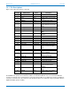
October 2017 BNO080 Datasheet 1000-3927 The maximum available data rates that can be configured per sensor are listed in Figure 6-14.
October 2017 BNO080 Datasheet Sensor Idle Power Gyro rotation Vector 6 and 9-Axis Sensor Fusion (Rotation Vector, Linear Acceleration, Gravity, Game Rotation Vector) Calibrated Gyroscope Geomagnetic Rotation Vector Calibrated Accelerometer Significant Motion Detector Step counter/detector Tap detector Shake gesture Stability Classifier Stability detector Sensor Rate (Hz) 1000-3927 Current (mA) VDDIO Rail — 0.12 Android Sensors 1000 7.14 400 7.10 100 3.50 200 5.34 Power VDD Rail 0.01 (mW) 0.39 7.
October 2017 BNO080 Datasheet 1000-3927 7 Packaging Information All information in this section is reproduced for convenience. Bosch Sensortec is the manufacturer of the physical BNO080 device. The reader should consult the BMF055 datasheet [5] for final verification. 7.1 Package Outline The BNO080 is available in a 28-pin Land Grid Array (LGA) package. Units are in mm. Note: Unless otherwise specified tolerance = decimal ±0.1mm. Figure 7-1: 28 pin LGA package outline (Image from Bosch) www.
October 2017 7.2 BNO080 Datasheet 1000-3927 Landing Pattern Recommendation 0.675 6 5 3 4 2 1 7 28 8 27 9 26 10 25 11 24 12 23 5.2 0.25 0.25 2.025 13 22 14 21 15 16 1.225 17 18 19 20 0.575 0.25 3.8 Figure 7-2: Landing pattern recommendation 7.3 Soldering Guidelines Bosch Sensortec publishes a handling, soldering & mounting guide. The reader should consult that guide for manufacturing guidelines [5]. 7.
October 2017 BNO080 Datasheet Symbol • T Name Pin 1 identifier Product number Second row C Third row 701 1000-3927 Remark — 3 numeric digits internal identification for product type 4-digits Internal use 3-digits Numerical counter Figure 7-3: Marking of mass production parts 7.
October 2017 BNO080 Datasheet 1000-3927 8 Version History Version 1.3 1.2 1.1 1.0 www.hillcrestlabs.com Changes Update IO voltages in Figure 6-3. Update Figure 6-13. Added latency measurements. Clarified sequence number description. Clarified continuation bit in length field of SHTP header. Clarified SHTP channel usage. Added header to Figure 5-1. Update performance table. Clarified need to support clock stretching for I2C interface. Corrected descriptions in pin table for ENV_SCL and ENV_SDA.
October 2017 BNO080 Datasheet 1000-3927 9 References 1. 2. 3. 4. 5. 6. 7. 8. 1000-3625 – SH-2 Reference Manual, Hillcrest Labs. 1000-3535 – Sensor Hub Transfer Protocol, Hillcrest Labs. Android Sensors HAL Overview, Google. (http://source.android.com/devices/sensors/index.html) I2C-bus specification and user manual, NXP Semiconductors. (http://www.nxp.com/documents/user_manual/UM10204.pdf) BMF055 datasheet, Bosch Sensortec. https://aebst.resource.bosch.
October 2017 BNO080 Datasheet 1000-3927 10 Notices Information furnished by Hillcrest Laboratories, Inc. (Hillcrest) is believed to be accurate and reliable. However, Hillcrest assumes no responsibility for its use, nor for any infringement of patents or other rights of third parties that may result from its use. Hillcrest reserves the right to make changes, corrections, modifications or improvements to this document at any time without notice.