
Data Sheet


MLX90393
Micropower Triaxis® Magnetometer Datasheet
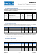
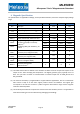
Parameter Remark Min Nom Max Unit
I
DD,CONVT
Conversion Current Temperature 1.60 2 mA
I
DD,STBY
Standby Current
(1)
43 60 µA
I
DD,IDLE
Idle Current
(2)
1 2.4 5 µA
I
DD,NOM
Nominal Current (TXYZ, Datarate =
10Hz, OSR=OSR2=0, DIG_FILT=4)
100 µA
(1) Standby current corresponds to the current consumed in the digital, where not the main oscillator is
running which is used for analog sequencing, but only the low-power oscillator. This standby
current is present in Burst mode; whenever the ASIC is counting down to start a new conversion.
(2) Idle current is the current that is drawn by the ASIC in the IDLE mode, where it can only receive new
commands on the communication bus, but all other blocks are disabled. The analog (excluding the
power-on-reset block) is disconnected, only the digital IO part allows clocking of a few vital gates.
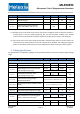
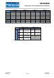
5. Timing Specification
The specifications are applicable at 25degC, unless specified otherwise, and for the complete supply voltage
range.
Parameter Remark Min Nom Max Unit
Main Oscillator & Derived Timings
T
STBY
Time from IDLE to STBY 400 500 600 µs
T
ACTIVE
Time from STBY to ACTIVE 8 µs
T
CONVM
Single Magnetic axis conversion time
(1)
typical programming range
0.192 66.56
ms
[(2+2^
DIG_FILT
)*2^
OSR
*0.064]
T
CONVT
Temperature conversion time
typical programming range
0.192 1.54
ms
[2^
OSR2
*0.192]
T
CONV_SMM
Total conversion time in Single
Measurement Mode
(1)
T
STBY
+ T
ACTIVE
+ m*T
CONVM
+ T
CONVT
ms
T
CONV_BURSTWOC
Total conversion time in BURST or WOC
Mode
(1)
T
ACTIVE
+ m*T
CONVM
+ T
CONVT
ms
T
OSC_TRIM
Trimming accuracy -5 +5 %
T
OSC_THD
Thermal drift (full temperature range) -5 +5 %
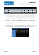
Low-power Oscillator & Derived Timings
T
INTERVAL
Time in between 2 conversions (Burst
mode or Wake-Up on Change)
(2)
0 1260
ms
BURST_DATA_RATE * 20
T
LPOSC_TRIM
Trimming accuracy -4 +4 %
T
LPOSC_THD
Thermal drift (full temperature range) -5 +5 %
3901090393 Data Sheet
Rev002 Page 3 Feb-2015