
Data Sheet

MLX90393
Micropower Triaxis® Magnetometer Datasheet
• Transmitting the Status Byte by the Slave, who is in control of the bus. Following the RR and RM
commands the sensor returns additional data bytes after the status byte.
• Acknowledging by the Master if the data is well received
• Generating a Stop condition (P) by the master
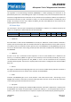
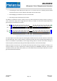
The Master controlled bus activity is shown in blue, the Slave controlled bus activity is shown in orange. In
case a command is longer than a single byte (see Table 6), the bytes are transmitted sequentially before
generating the Start Repeat (Sr) condition.
I2C_ADDR[6:0] W
ACK
S
COMMAND[7:0]
ACK
I2C_ADDR[6:0] R
ACK
Sr
STATUS_BYTE[7:0]
ACK
SCL
SDA
SCL
SDA
1 2 3 4 5 6 7 8 9 1 2 3 4 5 6 7 8 9
1 2 3 4 5 6 7 8 9
P
1 2 3 4 5 6 7 8 9
Figure 6: Default I2C communication example with status byte readback
The same applies to the Slave responses: following RR and RM commands, the Slave response is more than
just the Status Byte. There as well, the data is partitioned in bytes that are transmitted sequentially by the
slave. It is the Master’s responsibility to issue enough clocking pulses to read back all the data. Finding out
how many bytes is possible by decoding the Status Byte information, see Section Status Byte.
Finally the master is also free to not read back the status byte when issuing a command. In doing so, he
loses the ability to see if the command was received properly by the MLX90393. Moreover, the first SM
command issued by the master after power-up or reset should have the status byte read back in order to
get valid measurement data back.
3901090393 Data Sheet
Rev002 Page 16 Feb-2015