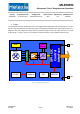
MLX90393 Micropower Triaxis® Magnetometer Datasheet Part No. Temperature Code Package Code Silicon Version Option Code Packing Format MLX90393 S (-20°C to 85°C) LW (QFN16 3x3mm) ABA 011 RE (Reel) 1. Scope This document holds the specification of a 3-axis magnetometer targeting low-power applications. The IC is based on the Hall-effect and the patented Triaxis® technology from Melexis.
MLX90393 Micropower Triaxis® Magnetometer Datasheet 2. Absolute Maximum Ratings The MLX90393 can withstand the conditions described in the table below for short periods of time; they do not constitute conditions for normal operation. Parameter Max Unit -0.3 4 V Digital IO Supply Limits -0.3 min(4, VDD+0.3) V TSTORAGE Storage (idle) temperature range -50 125 °C ESDHBM According to AEC-Q100-002 2.
MLX90393 Micropower Triaxis® Magnetometer Datasheet Parameter IDD,CONVT IDD,STBY Remark Min Conversion Current Temperature Standby Current (1) (2) IDD,IDLE Idle Current 1 IDD,NOM Nominal Current (TXYZ, Datarate = 10Hz, OSR=OSR2=0, DIG_FILT=4) Nom Max Unit 1.60 2 mA 43 60 µA 2.4 5 µA 100 µA (1) Standby current corresponds to the current consumed in the digital, where not the main oscillator is running which is used for analog sequencing, but only the low-power oscillator.
MLX90393 Micropower Triaxis® Magnetometer Datasheet Parameter Remark Min Nom Max Unit 0.6 1.5 ms 250 us Startup TPOR Power-on-reset completion time External Trigger TTRIG Trigger pulse width (active high) 0.01 (1) This conversion time is defined as the time to acquire a single axis of the magnetic flux density. When measuring multiple axes, they are obtained through time-multiplexing, i.e. X(t), Y(t+TCONVM) and Z(t+2*TCONVM).
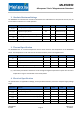
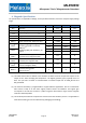
MLX90393 Micropower Triaxis® Magnetometer Datasheet DIG_FILT Maximum ODR for OSR2=0x0 [Hz] 0 1 2 3 4 5 6 7 0 716.9 622.7 493.0 348.0 219.2 125.9 68.0 35.4 OSR 1 2 3 493.0 303.4 171.5 408.0 241.5 133.0 303.4 171.5 91.8 200.6 108.6 56.6 119.6 62.6 32.1 66.1 33.9 17.2 34.9 17.7 8.9 18.0 9.0 4.
MLX90393 Micropower Triaxis® Magnetometer Datasheet 6. Magnetic Specification The specifications are applicable at 25degC, unless specified otherwise, and for the complete supply voltage range.
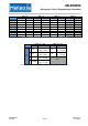
MLX90393 Micropower Triaxis® Magnetometer Datasheet GAIN_SEL 0 1 2 3 4 5 6 7 RES = 0 SENSXY SENSZ 0.805 1.468 0.644 1.174 0.483 0.881 0.403 0.734 0.322 0.587 0.268 0.489 0.215 0.391 0.161 0.294 RES = 1 SENSXY SENSZ 1.610 2.936 1.288 2.349 0.966 1.762 0.805 1.468 0.644 1.174 0.537 0.979 0.429 0.783 0.322 0.587 RES = 2 SENSXY SENSZ 3.220 5.872 2.576 4.698 1.932 3.523 1.610 2.936 1.288 2.349 1.073 1.957 0.859 1.566 0.644 1.174 RES = 3 SENSXY SENSZ 6.440 11.744 5.152 9.395 3.864 7.046 3.220 5.872 2.576 4.
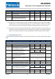
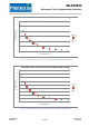
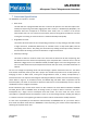
MLX90393 Micropower Triaxis® Magnetometer Datasheet XY-axis Noise over Conversion Time (bundled per OSR setting) 60 Noise Stdev [mGauss] 50 40 OSR = 0 30 OSR = 1 OSR = 2 20 OSR = 3 10 0 1 10 100 Conversion Time [ms] Figure 2: XY axis RMS noise versus conversion time, expressed in mGauss for GAIN_SEL = 0x7 Z-axis Noise over Conversion Time (bundled per OSR setting) 90 80 Noise Stdev [mGauss] 70 60 50 OSR = 0 OSR = 1 40 OSR = 2 30 OSR = 3 20 10 0 1 100 10 Conversion Time [ms] Figure
MLX90393 Micropower Triaxis® Magnetometer Datasheet 7. Functional Specification The MLX90393 can operate in 3 modes: • Burst mode The ASIC will have a programmable data rate at which it will operate. This data rate implies autowakeup and sequencing of the ASIC, flagging that data is ready on a dedicated pin (INT/DRDY). The maximum data rate corresponds to continuous burst mode, and is a function of the chosen measurement axes.
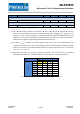
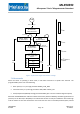
MLX90393 Micropower Triaxis® Magnetometer Datasheet POR VDD > VPOR_LH STARTUP TPOR LOAD CALIB DATA ~TINTERVAL WOC_IDLE LP_OSC enabled IDLE EX LP_OSC disabled TSTBY EX STANDBY ~TINTERVAL && Burst mode LP_OSC enabled TACTIVE MEASURE WOC mode MDATA ? LP_OSC & MAIN_OSC enabled T? X? Y? Z? m*TCONVM + TCONVT Burst mode SM mode TIME Figure 4: Top-level state diagram with indication of timings 7.
MLX90393 Micropower Triaxis® Magnetometer Datasheet the master have failed to read out any of them by the time the sensor has made a new conversion, the INT/DRDY pin will be strobed low for 10us, and the next rising edge will indicate a new set of data is ready. 7.2 Single Measurement mode Whenever the sensor is set to this mode (or after startup) the MLX90393 goes to the IDLE state where it awaits a command from the master to perform a certain acquisition.
MLX90393 Micropower Triaxis® Magnetometer Datasheet 8. Digital Specification The supported protocols are I2C and SPI.
MLX90393 Micropower Triaxis® Magnetometer Datasheet The argument in all mode-starting commands (SB/SW/SM) is a nibble specifying the conversions to be performed by the sensor in the following order «zyxt». For example, if only Y axis and temperature are to be measured in Single Measurement mode the correct command to be transmitted is 0x35h. The sequence of measurement execution on-chip is inverted to «TXYZ», so T will be measured before X, followed by Y and finally Z.
MLX90393 Micropower Triaxis® Magnetometer Datasheet 8.3 SPI Communication The MLX90393 can handle SPI communication at a bitrate of 10Mhz. The SPI communication is implemented in a half-duplex way, showing high similarities with I2C communication, but addressing through the \CS (Chip Select) pin instead of through bus arbitration. The half-duplex nature is at the basis of the supported 3-wire SPI operation.
MLX90393 Micropower Triaxis® Magnetometer Datasheet /CS SCL 1 MOSI 2 3 4 5 6 7 8 COMMAND[7:0] MISO 1 2 3 4 5 6 7 8 X (4-wire SPI) or Z (3-wire SPI) Z (3 & 4-wire SPI) STATUS_BYTE[7:0] NADD ADD Figure 5: SPI communication example 8.
MLX90393 Micropower Triaxis® Magnetometer Datasheet • Transmitting the Status Byte by the Slave, who is in control of the bus. Following the RR and RM commands the sensor returns additional data bytes after the status byte. • Acknowledging by the Master if the data is well received • Generating a Stop condition (P) by the master The Master controlled bus activity is shown in blue, the Slave controlled bus activity is shown in orange.
MLX90393 Micropower Triaxis® Magnetometer Datasheet 3901090393 Rev002 Page 17 Data Sheet Feb-2015
MLX90393 Micropower Triaxis® Magnetometer Datasheet 9. Memory Map The MLX90393 has 1kbit of non-volatile memory, and the same amount of volatile memory. Each memory consists out of 64 addresses containing 16 bit words. The non-volatile memory has automatic 2-bit error detection and 1-bit error correction capabilities per address. The handling of such corrections & detections is explained in Section Status Byte.
MLX90393 Micropower Triaxis® Magnetometer Datasheet The customer area houses 3 types of data: • Analog configuration bits • Digital configuration bits • Informative (free) bits The latter can be filled with customer content freely, and covers the address span from (and including) 0x0Ah to 0x1Fh, a total of 352 bits. The memory mapping of volatile and non-volatile memory on address level is identical. The volatile memory map is given in Figure 8.
MLX90393 Micropower Triaxis® Magnetometer Datasheet GAIN_SEL[2:0] : Analog chain gain setting, factor 5 between min and max code HALLCONF[3:0] : Hall plate spinning rate adjustment TRIG_INT_SEL : Puts TRIG_INT pin in TRIG mode when cleared, INT mode otherwise COMM_MODE[1:0] : Allow only SPI [10b], only I2C [11b] or both [0Xb] according to CS pin WOC_DIFF : Sets the Wake-up On Change based on Δ{sample(t),sample(t-1)} EXT_TRIG : Allows external trigger inputs when set, if TRIG_INT_SEL = 0 T
MLX90393 Micropower Triaxis® Magnetometer Datasheet 10. Packaging Specification 10.1 QFN package The MLX90393 shall be delivered in a QFN package as shown below in Figure 9. X Z Y Figure 9: Package Outline Drawing The sensing elements – Hall plates with the patented IMC technology – are located in the center of the die, which on its turn is located in the center of the package. The pinout (in name and function) is given in Table 7 below.
MLX90393 Micropower Triaxis® Magnetometer Datasheet # Name 1 Type Supply System Wiring Recommendation Primary Secondary Reference to I2C SPI 4-wire SPI 3-wire INT I/O out N/A VDD_IO optional optional optional 2 SENB/CS I/O in MLX Test VDD_IO to VDD_IO required required 3 SCL/SCLK I/O in MLX Test VDD_IO required required required 4 N/C 5 SDA/MOSI I/O bi MLX Test VDD_IO required required 6 MISO I/O out MLX Test VDD_IO floating required 7 INT/TRIG I/O bi
MLX90393 Micropower Triaxis® Magnetometer Datasheet 11.
MLX90393 Micropower Triaxis® Magnetometer Datasheet 12. ESD Precautions Electronic semiconductor products are sensitive to Electro Static Discharge (ESD). Always observe Electro Static Discharge control procedures whenever handling semiconductor products. 13.1 I2C A1 Recommended Application Diagram A0 13. A1 A0 I2C Address ------------------------------------Vss Vss 0001100R/W Vss Vdd 0001101R/W Vdd Vss 0001110R/W Vdd Vdd 0001111R/W R1=R2=10K C1=C2=0.1uF VDDIO (1.
MLX90393 Micropower Triaxis® Magnetometer Datasheet 14. Disclaimer Devices sold by Melexis are covered by the warranty and patent indemnification provisions appearing in its Term of Sale. Melexis makes no warranty, express, statutory, implied, or by description regarding the information set forth herein or regarding the freedom of the described devices from patent infringement. Melexis reserves the right to change specifications and prices at any time and without notice.
MLX90393 Micropower Triaxis® Magnetometer Datasheet 16. Table of Contents 1. Scope .......................................................................................................................................................................................................................1 2. Absolute Maximum Ratings ..................................................................................................................................................................................
MLX90393 Micropower Triaxis® Magnetometer Datasheet 17. Revision History Date Revision 11-Nov-2014 001 • First Document Release 16-Feb-2015 002 • • • Changed Ordering Code to indicate QFN wettable flanks Update Document number Added description of yellow cells in Table 1 and Table 2.