
Data Sheet

ams Datasheet Page 31
[v1-00] 2016-Nov-25 Document Feedback
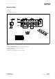
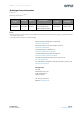
AS7263 − Detailed Description
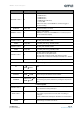
AT TCSMD=<value> OK
Set Sensor Mode
0 = BANK Mode 0;
1 = BANK Mode 1;
2 = BANK Mode 2;
3 = BANK Mode 3 One-Shot;
4 = Sensors OFF
In One-Shot mode, each ATTCSMD=3 command triggers a
One-Shot reading
AT TCSMD <value> OK Read Sensor Mode, see above
ATBURST=<value> OK
<value>= # of samples
(ATBURST=1 means run until ATBURST=0 is received (a special
case for continuous output)
LED Driver Controls
ATLED0=<value> OK Sets LED_IND: 100=ON, 0=OFF
ATLED0 <100|0>OK Reads LED_IND setting: 100=ON, 0=OFF
ATLED1=<value> OK Sets LED_DRV: 100=ON, 0=OFF
ATLED1 <100|0>OK Reads LED_DRV setting: 100=ON, 0=OFF
ATLEDC=<value> OK
Sets LED_IND and LED_DRV current
LED_IND: bits 3:0; LED_DRV: 7:4 bits
LED_IND: ‘b00=1mA; ‘b01=2mA; ‘b10=4mA; ‘b11=8ma
LED_DRV: ‘b00=12.5mA; ‘b01=25mA; ‘b10=50mA; ‘b11=100mA
ATLEDC <value>OK Reads LED_IND and LED_DRV current settings as shown above
NOP, Version Access, System Reset
AT
OK → Success
ERROR → Failure
NOP
ATRST None Software Reset – no response
AT VERSW
<SWversion#>→OK
ERROR → Failure
Returns the system software version number
AT VERHW
<HWversion#>→ OK
ERROR → Failure
Returns the system hardware revision and product ID, with bits
7:4 containing the part ID, and bits 3:0 yielding the chip revision
value.
Firmware Update
ATFWU=<value>OK
<value>= 16-bit checksum. Initial the firmware update process.
Bytes that follow is always 56k bytes
ATFW=<value>OK
Download new firmware
Up to 7 Bytes represented as hex chars with no leading or
trailing 0x.
Repeat command till all 56k bytes of firmware are downloaded
ATFWS OK
Causes the active image to switch between the two possible
current images and then resets the IC
Command Response Description / Parameters