
Data Sheet

ams Datasheet Page 29
[v1-00] 2016-Nov-25 Document Feedback
AS7263 − Detailed Description
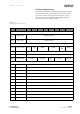
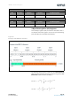
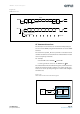
Figure 31:
UART Protocol
AT Command Interface
The microprocessor interface to control the NIR Spectral_ID
Sensor is via the UART, using the AT Commands across the UART
interface.
The 6-channel Spectral _ID sensor provides a text-based serial
command interface borrowed from the “AT Command” model
used in early Hayes modems.
For example:
• Read DATA value: ATDATA → <data>OK
• Set the gain of the sensor to 1x: ATGAIN =0 → OK
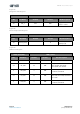
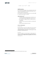
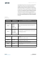
The “AT Command Interface Block Diagram”, shown below be-
tween the network interface and the core of the system, pro-
vides access to the Spectral_ID engine’s control and configura-
tion functions.
Figure 32:
AT Command Interface Block Diagram
Start Bit
TX
D0
D1 D2 D3 D4 D5 D6
D7 D0
D0
D1 D2 D3 D4 D5 D6
D7 D0
T
bit
=1/Baude Rate
Stop Bit Next Start
Sample Points
Start Bit detected
After T
bit
/2: Sampling of Start Bit
After T
bit
: Sampling of Data
RX
P
Parity Bit
P
Always Low Always HighEven or odd
Data Bits
AT Command Interface
Spectral_ID
Engine
AT
Command
Interface
RX
uP
TX
AS726x
AT Command Interface
AT Commands