
Data Sheet

ams Datasheet Page 15
[v1-00] 2016-Nov-25 Document Feedback
AS7263 − Detailed Description
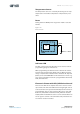
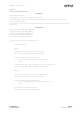
Figure 15:
Photo Diode Array
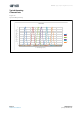
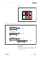
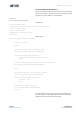
Figure 16:
Bank Mode and Data Conversion
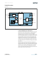
RC Oscillator
The timing generation circuit consists of an on-chip 16MHz,
temperature compensated oscillator, which provides the mas-
ter clock for the AS7263.
T U S
R V W
Photo Diode Array
BANK Mode 0
On e Conversion S, T, U, V
Integration Time
R, T, U, W
On e Conversion
BANK Mode 1
Integration Time
S, T, U, V
1st Conversion
BANK Mode 2
Integration Time
R, T, U, W
2nd Conversion
Integration Time