
Data Sheet

Page 8 ams Datasheet
Document Feedback [v1-01] 2017-Mar-17
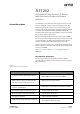
AS7262 − Timin g Charac teristics
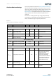
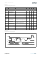
Figure 7:
AS7262 I²C Slave Timing Characteristics
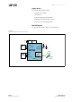
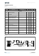
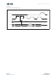
Figure 8:
I²C Slave Timing Diagram
Symbol Parameter Conditions Min Typ Max Unit
I²C Interface
f
SCLK
SCL Clock Frequency 0 400 kHz
t
BUF
Bus Free Time Between a STOP
and START
1.3 µs
t
HS:STA
Hold Time (Repeated) START 0.6 µs
t
LOW
LOW Period of SCL Clock 1.3 µs
t
HIGH
HIGH Period of SCL Clock 0.6 µs
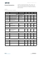
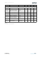
t
SU:STA
Setup Time for a Repeated START 0.6 µs
t
HS:DAT
Data Hold Time 0 0.9 µs
t
SU:DAT
Data Setup Time 100 ns
t
R
Rise Time of Both SDA and SCL 20 300 ns
t
F
Fall Time of Both SDA and SCL 20 300 ns
t
SU:STO
Setup Time for STOP Condition 0.6 µs
C
B
Capacitive Load for Each Bus Line
CB — total capacitance of
one bus line in pF
400 pF
C
I/O
I/O Capacitance (SDA, SCL) 10 pF
Timing Characteristics
SCL
SDA
t
SU:STA
t
LOW
t
HIGH
t
F
t
R
t
HD:STA
t
SU:STO
t
SU:DAT
t
HD:DAT
t
BUF
V
IH
V
IL
PS SP
Stop Start