
Data Sheet

ams Datasheet Page 31
[v1-01] 2017-Mar-17 Document Feedback
AS7262 − Detailed Description
AT Command Interface
The microprocessor interface to control the Visible Spectral_ID
sensor is via the UART, using the AT Commands across the UART
interface.
The 6-channel Spectral _ID sensor provides a text-based serial
command interface borrowed from the “AT Command” model
used in early Hayes modems. For example:
• Read DATA value: ATDATA → <data>OK
• Set the gain of the sensor to 1x: ATGAIN =0 → OK
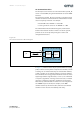
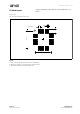
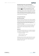
The “AT Command Interface Block Diagram”, shown below
between the network interface and the core of the system,
provides access to the Spectral_ID engine’s control and
configuration functions.
Figure 30:
AT Command Interface Block Diagram
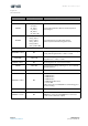
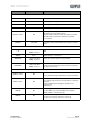
In Figure 31, numeric values may be specified with no leading
prefix, in which case they will be interpreted as decimals, or with
a leading “0x” to indicate that they are hexadecimal numbers,
or with a leading “‘b” to indicate that they are binary numbers.
The commands are loosely grouped into functional areas. Texts
appearing between angle brackets (‘<‘ and ‘>‘) are commands
or response arguments. A carriage return character, a linefeed
character, or both may terminate commands and responses.
Note that any command that encounters an error will generate
the “ERROR” response shown, for example, in the NOP
command at the top of the first table, but has been omitted
elsewhere in the interest of readability and clarity.
AT Command Interface
Spectral_ID
Engine
AT
Command
Interface
RX
μP
TX
AS726x
AT Command Int erface
AT Commands