
Data Sheet

Page 30 ams Datasheet
Document Feedback [v1-01] 2017-Mar-17
AS7262 − Detailed Description
UART Interface
If selected by the I²C_ENB pin setting, the UART module
implements the TX and RX signals as defined in the RS-232 /
V.24 standard communication protocol.
It has on both, receive and transmit path, a 16 entry deep FIFO.
It can generate interrupts as required.
UART Feature List
1
• Full Duplex Operation (Independent Serial Receive and
Transmit Registers) with FIFO buffer of 8 byte for each.
• At a clock rate of 16MHz it supports communication at
115200 Baud.
• Supports Serial Frames with 8 Data Bits, no Parity and 1
Stop Bit
Theory of Operation
Transmission
If data is available in the transmit FIFO, it will be moved into the
output shift register and the data will be transmitted at the
configured Baud Rate, starting with a Start Bit (logic zero) and
followed by a Stop Bit (logic one).
Reception
At any time, with the receiver being idle, if a falling edge of a
start bit is detected on the input, a byte will be received and
stored in the receive FIFO. The following Stop Bit will be checked
to be logic one.
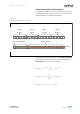
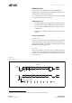
Figure 29:
UART Protocol
1. With UART operation, min VDD of 2.97V is required as shown in Electrical Characteristics Figures.
Start Bit
TX
D0
D1 D2 D3 D4 D5 D6
D7 D0
D0
D1 D2 D3 D4 D5 D6
D7 D0
T
bit
=1/Baude Rate
Stop Bit Next Start
Sample Points
Start Bit detected
After T
bit
/2: Sampling of Start Bit
After T
bit
: Sampling of Data
RX
Always Low Always High
Data Bits