
Data Sheet

ams Datasheet Page 25
[v1-01] 2017-Mar-17 Document Feedback
AS7262 − Detailed Description
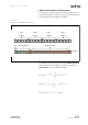
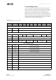
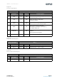
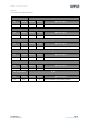
Figure 23:
Control Setup Register
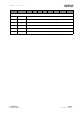
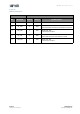
Figure 24:
Integration Time Register
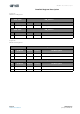
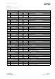
Figure 25:
Device Temperature Register
Addr: 0x04/0x84 Control_Setup
Bit Bit Name Default Access Bit Description
7RST 0R/W
Soft Reset, Set to 1 for soft reset, goes to 0
automatically after the reset
6INT 0R/W
Enable interrupt pin output (INT),
1: Enable, 0: Disable
5:4 GAIN 0 R/W
Sensor Channel Gain Setting (all channels)
‘b00=1x; ‘b01=3.7x; ‘b10=16x; ‘b11=64x
3:2 BANK 10 R/W
Data Conversion Type (continuous)
‘b00=Mode 0; ‘b01=Mode 1; ‘b10=Mode 2;
‘b11=Mode 3 One-Shot
1 DATA_RDY 0 R/W
1: Data Ready to Read, sets INT active if interrupt is
enabled.
Can be polled if not using INT.
0 RSVD 0 R Reserved; Unused
Addr: 0x05/0x85 INT_T
Bit Bit Name Default Access Bit Description
7:0 INT_T 0xFF R/W Integration time = <value> * 2.8ms
Addr: 0x06 Device_Temp
Bit Bit Name Default Access Bit Description
7:0 Device_Temp R Device temperature data byte (°C)