
Data Sheet

Page 22 ams Datasheet
Document Feedback [v1-01] 2017-Mar-17
AS7262 − Detailed Description
I²C Virtual Register Set
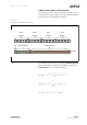
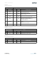
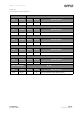
Figure 20 provides a summary of the AS7262 I²C register set.
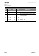
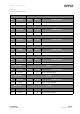
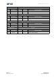
Figures after that provide additional register details. All register
data is hex, and all multi-byte entities are Big Endian (most
significant byte is situated at the lowest register address).
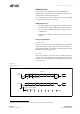
Multiple byte registers (2 byte integer, or, 4 byte floating point)
must be read in the order of ascending register addresses (low
to high). And if capable of being written to, must also be written
in the order of ascending register addresses.
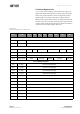
Figure 20:
I²C Virtual Register Set Overview
Addr Name <D7> <D6> <D5> <D4> <D3> <D2> <D1> <D0>
Version Registers
0x00:0x01 HW_Version Hardware Version
0x02:0x03 FW_Version Firmware Version
Control Registers
0x04 Control_Setup RST INT GAIN Bank DATA_RDY RSVD
0x05 INT_T Integration Time
0x06 Device_Temp Device Temperature
0x07 LED_Control RSVD ICL_DRV
LED_DRV
ICL_IND LED_IND
Sensor Raw Data Registers
0x08 V_High Channel V High Data Byte
0x09 V_Low Channel V Low Data Byte
0x0A B_High Channel B High Data Byte
0x0B B_Low Channel B Low Data Byte
0x0C G_High Channel G High Data Byte
0x0D G_Low Channel G Low Data Byte
0x0E Y_High Channel Y High Data Byte
0x0F Y_Low Channel Y Low Data Byte
0x10 O_High Channel O High Data Byte
0x11 O_Low Channel O Low Data Byte
0x12 R_High Channel R High Data Byte
0x13 R_Low Channel R Low Data Byte