
Data Sheet

Page 18 ams Datasheet
Document Feedback [v1-01] 2017-Mar-17
AS7262 − Detailed Description
I²C Feature List
• Fast mode (400kHz) and standard mode (100kHz) support.
• 7+1-bit addressing mode.
• Write format: Byte.
• Read format: Byte.
• SDA input delay and SCL spike filtering by integrated
RC-components.
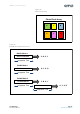
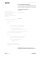
Figure 18:
I²C Slave Device Address and Physical Registers
I²C Virtual Register Write Access
I²C Virtual Register Byte Write shows the pseudocode necessary
to write virtual registers on the AS7262. Note that, because the
actual registers of interest are realized as virtual registers, a
means of indicating whether there is a pending read or write
operation of a given virtual register is needed. To convey this
information, the most significant bit of the virtual register
address is used as a marker. If it is 1, then a write is pending,
otherwise the slave is expecting a virtual read operation. The
pseudocode illustrates the proper technique for polling of the
I²C slave status register to ensure the slave is ready for each
transaction.
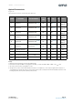
Entity Description Note
Device Slave Address 8-bit Slave Address
Byte = 1001001x (device address = 49 hex)
x= 1 for Master Read (byte = 93 hex)
x= 0 for Master Write (byte = 92 hex)
STATUS Register
I²C slave interface
STATUS register
Read-only
Register Address = 0x00
Bit 1: TX_VALID
0 → New data may be written to WRITE register
1 → WRITE register occupied. Do NOT write.
Bit 0: RX_VALID
0 → No data is ready to be read in READ register.
1 → Data byte available in READ register.
WRITE Register
I²C slave interface
WRITE register
Write-only
Register Address = 0x01
8-Bits of data written by the I²C Master intended
for receipt by the I²C slave. Used for both virtual
register addresses and write data.
READ Register
I²C slave interface
READ register
Read-only
Register Address = 0x02
8-Bits of data to be read by the I²C Master.