
Data Sheet

[AK9753]
017005237-E-00 2017/04
- 8 -
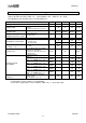
9. Power Supply Conditions
(Unless otherwise specified, VDD=1.71 ~ 3.63V, DVDD= 1.65V ~ VDD, Ta= -30 ~ 85ºC)
Parameter
Symbol
Min.
Typ.
Max.
Unit
Power Supply Rise Time
(* 4, * 5)
Time until VDD, DVDD,
and PDN are set to the
operating voltage from
0.2V.
VDD pin,
DVDD pin
PSUP
50
ms
Power-on Reset Time
(* 4, * 5)
Time until AK9753
becomes Power down
Mode after PSUP.
VDD pin
PORT
3000
µs
Shutdown Voltage
(* 5, * 6)
Shutdown Voltage for
POR re-starting.
VDD pin,
DVDD pin
SDV
0.2
V
Power Supply Interval Time
(* 4, * 5, * 6)
Voltage retention time
below SDV1 for POR
re-starting.
VDD pin,
DVDD pin
PSINT
3000
µs
Notes:
* 4. Reference data only, not tested.
* 5. Power-on Reset circuit detects the rising edge of VDD, resets the internal circuit, and initializes the
registers. After Power-on reset, Stand-by Mode is selected.
* 6. The condition that POR surely works at the power-up the power-up again after power supply goes
down. Unless this condition is satisfied, the reset may not be correctly expected.
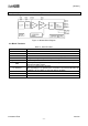
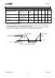
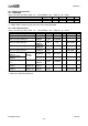
0V
PSINT: 3000µs
PSUP: 50ms
PORT: 3000µs
Stand-by Mode
VDD/DVDD/PDN
SDV: 0.2V
Stand-by Mode
Figure 9.1. Power Supply Conditions