
Data Sheet

[AK9753]
017005237-E-00 2017/04
- 4 -
4. Block Diagram and Functions
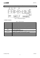
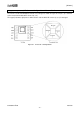
4.1. Block Diagram
Figure 4.1 AK9753 Block Diagram
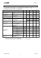
4.2. Block Functions
Table 4.1. Block Functions
Block
Function
4 x IR
Four IR Sensor
MUX
Matrix Switch
TIA
Photocurrents of IR Sensor are converted to voltage signals.
AMP
Programmable gain amplifier to adjust the outputs.
Temperature Sensor
Built-in Temperature Sensor
ADC
The amplifier output and the built-in temperature sensor output are
converted to digital signals.
I
2
C Interface
Interface to external host controller.
SCL and SDA pins are provided for I
2
C Interface. The interface operates up
to 400kHz rate and down to 1.65V low voltage condition.
EEPROM
EEPROM
OSC
Internal Oscillator.
POR
Power On Reset circuit.