
Data Sheet

[AK9753]
017005237-E-00 2017/04
- 38 -
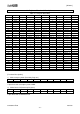
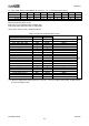
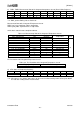
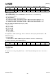
12). EINTEN: Interrupt Source setting (Read / Write Registers)
Address
Name
D7
D6
D5
D4
D3
D2
D1
D0
1BH
EINTEN
IR13HI
IR13LI
IR24HI
IR24LI
DRI
Reset
1
1
0
0
0
0
0
0
The interrupt to the HOST MCU via the INT output can be obtained by the following methods: INT output
turns to “Active”, when at least one of the enabled interrupt source conditions is satisfied. HOST MCU
can identify the interrupt source by reading the Interrupt Source Status (INST).
When DRI and threshold Level interrupt (IR13HI, IR13LI, IR24HI and IR24LI) are simultaneously set to
“Enable”, the priority is given to threshold level interrupt.
DRI: Data ready interrupt setting
“0”: Interrupt Disable
“1”: Interrupt Enable
Setting DRI bit to “1” enables the interrupt function at the timing of data ready.
IR13HI / IR24HI: Upper threshold level interrupt setting
“0”: Interrupt Disable
“1”: Interrupt Enable
Setting IR13H / IR24HI bit to “1” enables the interrupt function at the timing in which the differential
output (IR1 - IR3 / IR2 - IR4) changes from the level which is below the upper threshold level to the level
which is above the upper threshold level, or at the timing in which the differential output (IR1 - IR3 / IR2 -
IR4) changes from the level which is above “the upper threshold level - hysteresis” to the level which is
below “the upper threshold level - hysteresis”.
IR13LI / IR24LI: Lower threshold level interrupt setting.
“0”: Interrupt Disable
“1”: Interrupt Enable
Setting IR13LI/IR24LI bit to “1” enables the interrupt function at the timing in which the differential output
(IR1 - IR3 / IR2 - IE4) changes from the level which is above the lower threshold level to the level which
is below the lower threshold level, or at the timing in which the differential output (IR1 - IR3 / IR2 - IR4)
changes from the level which is below “the lower threshold level +hysteresis” to the level which is above
“the lower threshold level +hysteresis.